- ▶
- Heaters/Source
- ▶
- Agilent Heaters and SensorsMass Spectrometry, Scientific Supplies & ManufacturingScientific Instrument Services 5973 Source Heater Tamper Resistant Allen Wrench 5973/5975 Quad Sensor 5985 Source Heater Assembly Agilent Interface Heater Assembly 5971 Interface Heater

- ▶
- Reference Material on InstrumentationArticle - A High Temperature Direct Probe for a Mass Spectrometer Design of a Direct Exposure Probe and Controller for use ona Hewlett-Packard 5989 Mass Spectrometer SIS AP1000 AutoProbe™ SIS AP2000 AutoProbe™ - Description of System HPP7: Direct Probe Electronics Console HPP7: Direct Probe for the Agilent (HP) 5973/5975 MSD HPP7: HP Direct Probe Application Notes HPP7: Installation Directions for the Direct Probe HPP7: Side Cover for the HP 5973 MSD HPP7: Support HPP7: Probe Inlet System for the Agilent (HP) 5973 and 5975 MSD with Automatic Indexed Stops HPP7: Theory of Operation of the Direct Probe and Probe Inlet System Direct Thermal Extraction Thermal Desorption Application Notes Environmental Thermal Desorption Application Notes Food Science Thermal Desorption Application Notes Forensic Thermal Desorption Application Notes GC Cryo-Trap Application Notes Headspace Application Notes Purge & Trap Thermal Desorption Application Notes Theory of Operation of the AutoDesorb® System AutoDesorb Notes for SIS Dealers Adsorbent Resin Application Notes Installation of the Short Path Thermal Desorption System on Agilent (HP) and Other GCs Installation of the Short Path Thermal Desorption System on a Varian 3400 GC AutoDesorb® System Development Team Thermal Desorption Applications and Reference Materials Installation of the Short Path Thermal Desorption System - TD5 Part I - Design & Operation of the Short Path ThermalDesorption System Installation Instructions for the Model 951 GC Cryo-Trap on the HP 5890 Series GC Installation Instructions for the Model 961 GC Cryo-Trap on the HP 5890 Series GC Operation of the Model 951/961 GC Cryo-Trap SIS GC Cryo Traps - Theory of Operation NIST/EPA/NIH Mass Spectral Enhancements - 1998 version (NIST98) SIMION 3D Ion Optics Class Mass Spectrometer Source Cleaning Methods MS Tip: Mass Spectrometer Source Cleaning Procedures Mass Spec Source Cleaning Procedures Micro-Mesh® Abrasive Sheets Research Papers Using New Era Syringe Pump Systems EI Positive Ion Spectra for Perfluorokerosene (PFK) Cap Liner Information How do I convert between fluid oz and milliliters? Which bottle material should I choose? Which bottle mouth should I choose? The Bottle Selection Guide CGA Connections for Gas Tanks Chemical Reaction Interface Mass Spectrometry (CRIMS)

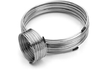
- Instrument Tubing
- ▶
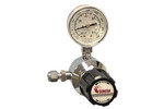
- Gas RegulatorsModel 3530 Series - Single Stage Purity Brass Regulator Model 3510 Series - Single Stage High Purity Stainless Steel Regulators Model 3120 Series - Dual Stage Purity Brass Regulator Model 3810 Series - Dual Stage High Purity Stainless Steel Regulators Tescom Gas Line Regulators 3420 Series Tescom Gas Line Regulators 3450 Series Concoa In-Line Regulators Model 304 Series Concoa In-Line Regulators Model 324 Series
- TD
- ▶
- AccessoriesTD Supply Kit Desorption Tubes Adsorbent Resins Desorption Tube Needles Desorption Tube Seals Desorption System Fittings GC Cryo-Trap Extraction Cell TD Sample Loader Prepacked, Conditioned Desorption Tubes Desorption Tube Packing Accessories Stainless Steel Purge Heads Injection Port Liners Tenax TA Poster TD Application Notes Customer Service
- GCColumns Fused Silica Tubing Instrument Tubing Injection Port Liners Septa by Manufacturer SIS GC Cryo-Traps Ferrules Valves Swagelok® Fittings Pyrolysis Probe Accessories Gas Generators Gas Regulators Gas Purifiers and Filters Syringes SGE MEPS™-Micro Extraction by Packed Sorbent Purge and Trap System SGE SilFlow™ Stainless Steel Micro-Fluidic Platform Accessories NIST GC RI Library Other GC Supplies Catalog Page D1
- ▶
- GC Cryo-traps
- LiteratureApplication Notes Adsorbent Resins Guide Mass Spec Tips SDS Sheets FAQ MS Calibration Compound Spectra Manuals MS Links/Labs/ Organizations MS Online Tools Flyers on Products/Services Scientific Supplies Catalog About Us NextAdvance Bullet Blender® Homogenizer Protocols Micro-Mesh® Literature Instrumentation Literature Agilent GC/MS Literature SIS News / E-Mail Newsletter NIST MS Database - Update Notifications
- ▶
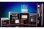
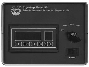
- Operation of the Model 951/961 GC Cryo-Trap (This Page)

Description of the Electronics Console
|
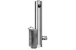
Model 951 (CO2 coolant) |
 Model 961 (LN2 coolant) |
Figure # 16 - Electronics Console
The electronics Console front panel consists of a main power switch, a rotary select switch and the digital dual temperature controller module.
Main Power Switch
The Power switch controls the power to the entire Cryo-Trap Electronics Console as well as the Cryo-Trap module. When this switch is turned OFF, neither heating power nor cooling liquid is input to the Cryo-Trap module. When the Cryo-Trap is not being used, it should be left in the OFF position.
Rotary Select Switch
The rotary select switch permits the selection of the mode of operation. In the OFF position no heating power or liquid cooling (CO2 for the Model 951 or LN2 for the Model 961) is being supplied to the Cryo-Trap module. This is the normal standby position when the Cryo-Trap is not being actively utilized to trap or analyze a sample. In the COOL position, liquid coolant is supplied to the Cryo-Trap module to cool this module down to its preset cooling point which has been pre selected and set via channel 2 on the temperature controller. The system will regulate and hold near this preset cooling temperature in the COOL position. In the HEAT position, current is supplied to the Cryo-Trap module to regulate its temperature to the temperature which has been pre selected via channel 1 on the temperature controller. Both the HEAT and COOL positions on this rotary switch are designed for the manual operation of the Cryo-Trap. They can also be utilized to override or supplement the operation of the automatic mode of operation.
The AUTO position on the rotary switch is designed for automatic operation and control of the heating and cooling cycles of the Cryo-Trap via an external input to the Electronics Console from an external device such as the S.I.S. Short Path Thermal Desorption System or other appropriate system. This controlling signal is provided via the remote input connector on the back of the Electronics Console. The input consists of two wires. When these wires are shorted, via a closure of a switch between these two inputs, the Cryo-Trap channel 2 is activated, which causes the system to operate in the COOL mode. When these wires are open, the Cryo-Trap operates in the HEAT mode and is controlled and regulated via channel 1 on the temperature controller.
NOTE ON COOLING (concerning CO2 only)
The 951 Cryo-Trap is programmed to turn the liquid CO2 OFF and ON at 2 second timed intervals when the difference between the preset COOL temperature and the actual temperate is greater than 30 degrees. This has been programmed in this manner for the optimum performance of the Cryo-Trap. It controls the rate of cooling of the Cryo-Trap and prevents dry ice plugs from clogging the system. As soon as the difference between the preset COOL temperature and the actual Cryo-Trap temperature is less than 30 degrees, the C02 coolant will remain on until the temperatures become equal at which point the controller will regulate and control the Cryo-Trap at the COOL selected temperature.
Digital Dual Temperature Controller
The Digital Dual Temperature Controller permits the user to input both the cryo cooling set point temperature for trapping volatiles in the Cryo-Trap module and the Heating set point temperature to elute the volatiles from the Cryo-Trap module. A single thermocouple in the Cryo-Trap module provides the temperature signal feedback to the temperature controller to control and regulate both of these temperatures. The heating cycle temperatures are controlled via Channel 1 on the temperature controller and the cryo cooling cycles are controlled via Channel 2 on the temperature controller. The red LED display panel shows the actual temperature in degrees Centigrade when the letter "C" is displayed in the last right digit of the LED display.
In order to set the heating and cooling temperatures to the users requirements, the SET button on the Temperature Controller should be pushed once. When this is done, the display will indicate a flashing "S" in the last right digit of the LED display. The left digits will display the current setting for the temperature and either " 1 " or "2" will be lit at the bottom of the display. A " 1 " indicates that the Channel 1 temperature or the heating preset temperature is being displayed and can be changed by the user at this time. To change the temperature use the two arrow keys to either raise or lower the temperature to the required value. When finished, push the SET button again. The new pre selected heating temperature has been stored and the system is ready for the next input. A "2" indicates that Channel 2 temperature or the Cooling temperature is being displayed and can be changed by the user. Use the two arrow keys to select the required COOL temperature. When finished, push the SET button once again. Both the heating and cooling values selected are now stored in the controller and will remain in the controller even if the main power switch is turned OFF. After the new set points have been input to the temperature controller, the display should once again read the current Cryo-Trap temperature in degrees C and the letter "C" should appear in the right digit of the LED display.
NOTE: After you push the SET button to input data, the temperature will wait 10 seconds for you to input or change the temperature settings. If no input is received within 10 seconds, the controller will exit the temperature edit mode and automatically return to the standard operating mode.
NOTE: Channel 1 (heating mode) only operates the heater in the Cryo-Trap. This circuit cannot cool down below room temperature. Likewise Channel 2 (cooling mode) only operates a valve which regulates the cooling of the Cryo-Trap. This circuit cannot heat the Cryo-Trap above room temperature.
Cryo-Trap Standard Operating Methodology
Modes of Operation
The GC Cryo-Trap has two basic modes of operation, manual and automatic. The automatic mode is designed to operate with the S.I.S. Short Path Thermal Desorption System, the GC as described later in this manual, or other systems configured to operate using the remote cable to switch between heating and cooling. In the manual mode of operation, the system can be switched from heating to cooling, manually via the rotary switch on the front panel of the Electronic console for the GC Cryo-Trap system.
Manual Mode
(1) Select the desired Cryo-Trap temperatures for both the Cooling and Heating cycles as described above. Normally a heating temperature between 100 and 250 degrees C is used for the release of the trapped volatiles from the Cryo-Trap. Use care not to exceed the maximum temperature of the guard column. A Cryo-Cooling temperature between 0 degrees and -70 degrees C (for CO2) or 0 degrees and -180 degrees C (for LN2) is normally used for the trapping of the volatile organics in the Cryo-Trap. The temperature you select depends on the compounds being analyzed.
(2) After the GC column is cooled down to its initial starting position as set by the GC, turn the rotary switch on the Cryo-Trap to the COOL position. This will cool the Cryo-Trap module down to the required cooling temperature. When the cooling temperature is reached, the GC samples can be injected into the GC injection port for subsequent trapping in the Cryo-Trap.
(3) When the sampling is complete, turn the rotary switch on the Cryo-Trap to the HEAT position and begin the GC column temperature program. The Cryo-Trap will rapidly heat up to the pre selected heating temperature to elute the volatiles from the guard column inside the Cryo-Trap module and elute these organics through the GC column.
(4) When the GC run is complete, turn the rotary switch to the OFF position until ready for the next sample to be analyzed.
Automatic Mode of Operation
(1) Select the desired Cryo-Trap temperatures for both the Cooling and Heating cycles as described above. Normally a heating temperature between 100 and 250 degrees C is used for the release of the trapped volatiles from the Cryo-Trap. Use care not to exceed the maximum temperature of the guard column. A Cryo-Cooling temperature between 0 and -70 degrees C is normally used for the trapping of the volatile organics in the Cryo-Trap. The temperature you select depends on the compounds being analyzed.
(2) After the GC column is cooled down to its initial starting position, turn the rotary switch on the Cryo-Trap to the AUTO position. The temperature cycle of the Cryo-Trap is now controlled via the input from the remote cable as described previously.
(3) The remote device should be set up to cool the Cryo-Trap module down to the required cooling temperature (input connections are closed or shorted). When the cooling temperature is reached, the GC samples can be injected into the GC injection port for subsequent trapping in the Cryo-Trap.
(4) When the sampling is complete, the remote device should switch to the heating cycle and begin the GC column temperature program (input connection are open). The Cryo-Trap will rapidly heat up to the pre selected heating temperature to elute the volatiles from the guard column inside the Cryo-Trap module and elute these organics through the GC column.
(5) When the GC run is complete, the rotary switch can be left in the AUTO position until ready for the next sample to be analyzed.
Operation of the Cyro-Trap with the S.I.S. Short Path Thermal Desorption System
(1) Select the desired Cryo-Trap temperatures for both the Cooling and Heating cycles as described above. Normally a heating temperature between 100 and 250 degrees C is used for the release of the trapped volatiles from the Cryo-Trap. Use care not to exceed the maximum temperature of the guard column. A Cryo Cooling temperature between 0 and -70 degrees C (for CO2) or 0 and -180 degrees C (for LN2) is normally used for the trapping of the volatile organics in the Cryo-Trap. The temperature you select depends on the compounds being analyzed.
(2) After the GC column is cooled down to its initial starting position, turn the rotary switch on the Cryo-Trap to the AUTO position. The temperature cycle of the Cryo-Trap is now controlled via the input from the remote cable connected to the remote input 2 on the Short Path Thermal Desorption System as described previously.
(3) The Cooling cycle for the Cryo-Trap can be started by one of two methods
- (a) When the "Auto Start" button on the Short Path Thermal Desorption System is pushed, the Cryo-Trap will switch to the cooling cycle. This mode can be used as long as the purge gas time is sufficient to allow the Cryo-Trap to reach its initial cooling temperature. If this time is not sufficient or the user does not wish to purge the sample for this period of time, then the following method should be used.
- (b) When the "Gas" button on the S.P.T.D. system is pushed, the Cooling cycle will be activated. This also turns on the Gas through the desorption tube. The "Gas" button can be pushed off immediately to turn the purge gas off through the desorption tube, but the Cryo-Trap will remain in the cooling mode. The Cryo-Trap can only be switched back to the heating mode by pushing the "Stop/Reset" button on the Thermal Desorption System to reset the Desorption System Software.
(4) When the cooling temperature is reached, the "Auto Start" button on the Thermal Desorption System can be pushed to initiate the Desorption Process. The GC samples are injected into the GC injection port for subsequent trapping in the Cryo-Trap.
(5) When the sampling is complete, the Thermal Desorption System will automatically switch the Cryo-Trap to the heating cycle and begin the GC column temperature program (input connection are open). The Cryo-Trap will rapidly heat up to the pre selected heating temperature to elute the volatiles from the guard column inside the Cryo-Trap module and elute these organics through the GC column.
(6) When the GC run is complete, the rotary switch can be left in the AUTO position until ready for the next sample to be analyzed. The Cryo-Trap will remain in the heating mode until the Cooling Cycle is initialized as described above in step 3.