- ▶
- Heaters/Source
- ▶
- Agilent Heaters and SensorsMass Spectrometry, Scientific Supplies & ManufacturingScientific Instrument Services 5973 Source Heater Tamper Resistant Allen Wrench 5973/5975 Quad Sensor 5985 Source Heater Assembly Agilent Interface Heater Assembly 5971 Interface Heater
- ▶
- Reference Material on InstrumentationArticle - A High Temperature Direct Probe for a Mass Spectrometer Design of a Direct Exposure Probe and Controller for use ona Hewlett-Packard 5989 Mass Spectrometer SIS AP1000 AutoProbe™ SIS AP2000 AutoProbe™ - Description of System HPP7: Direct Probe Electronics Console HPP7: Direct Probe for the Agilent (HP) 5973/5975 MSD HPP7: HP Direct Probe Application Notes HPP7: Installation Directions for the Direct Probe HPP7: Side Cover for the HP 5973 MSD HPP7: Support HPP7: Probe Inlet System for the Agilent (HP) 5973 and 5975 MSD with Automatic Indexed Stops HPP7: Theory of Operation of the Direct Probe and Probe Inlet System Direct Thermal Extraction Thermal Desorption Application Notes Environmental Thermal Desorption Application Notes Food Science Thermal Desorption Application Notes Forensic Thermal Desorption Application Notes GC Cryo-Trap Application Notes Headspace Application Notes Purge & Trap Thermal Desorption Application Notes Theory of Operation of the AutoDesorb® System AutoDesorb Notes for SIS Dealers Adsorbent Resin Application Notes Installation of the Short Path Thermal Desorption System on Agilent (HP) and Other GCs Installation of the Short Path Thermal Desorption System on a Varian 3400 GC AutoDesorb® System Development Team Thermal Desorption Applications and Reference Materials Installation of the Short Path Thermal Desorption System - TD5 Part I - Design & Operation of the Short Path ThermalDesorption System Installation Instructions for the Model 951 GC Cryo-Trap on the HP 5890 Series GC Installation Instructions for the Model 961 GC Cryo-Trap on the HP 5890 Series GC Operation of the Model 951/961 GC Cryo-Trap SIS GC Cryo Traps - Theory of Operation NIST/EPA/NIH Mass Spectral Enhancements - 1998 version (NIST98) SIMION 3D Ion Optics Class Mass Spectrometer Source Cleaning Methods MS Tip: Mass Spectrometer Source Cleaning Procedures Mass Spec Source Cleaning Procedures Micro-Mesh® Abrasive Sheets Research Papers Using New Era Syringe Pump Systems EI Positive Ion Spectra for Perfluorokerosene (PFK) Cap Liner Information How do I convert between fluid oz and milliliters? Which bottle material should I choose? Which bottle mouth should I choose? The Bottle Selection Guide CGA Connections for Gas Tanks Chemical Reaction Interface Mass Spectrometry (CRIMS)

- Probes
- LiteratureApplication Notes Adsorbent Resins Guide Mass Spec Tips SDS Sheets FAQ MS Calibration Compound Spectra Manuals MS Links/Labs/ Organizations MS Online Tools Flyers on Products/Services Scientific Supplies Catalog About Us NextAdvance Bullet Blender® Homogenizer Protocols Micro-Mesh® Literature Instrumentation Literature Agilent GC/MS Literature SIS News / E-Mail Newsletter NIST MS Database - Update Notifications

- ▶
- SIS AP2000 AutoProbe™ - Description of System (This Page)
New Automated Direct Insertion Probe for the PolarisQ™ and TRACE DSQ™ Mass Spectrometers from Thermo Electron Corp.
|
SIS AP2000 attached to the PolarisQ or TRACE DSQ. |
The AutoProbe™ System is an Automated Direct Exposure Probe (DEP) for the Finnigan PolarisQ™ and TRACE DSQ™ Mass Spectrometer Systems. The AutoProbe™ System injects samples directly into the MS source for mass spec sample analysis with no chromatographic separation. This permits samples to be analyzed in 3 minutes or less. The AutoProbe™ operates in the Thermo Finnigan Xcalibur™ MS Software environment and is fully integrated with the Xcalibur™ software, including system setup, methods setup, system operation and data storage.
The direct probe was one of the earliest techniques used to introduce
samples into a mass spectrometer. The technique is still popular
today because it provides a means to perform rapid sample analysis
with minimal or no sample preparation. The electron impact (EI) mass
spectrometer mode of operation can be used when the sample to be
analyzed is relatively pure or when chromatographic separation of a
mixture is not required. Direct probe analysis has also been widely
used with Chemical Ionization (CI) mass spectrometry. The simplicity
of the CI spectrum permits the analysis of mixtures, whose spectra are
difficult to interpret using the EI mode of operation.
Applications of the direct probe technique include the screening of
drug and pharmaceutical samples, quality control sample analysis, spot
analysis of chemical reaction mixtures to monitor rates of synthesis,
and the analysis of compounds which cannot be chromatographed. The
AutoProbe System is used where high volumes of samples need to be
analyzed quickly or it can be used in an "Open Access"
environment where it can be used by multiple users with minimal MS
expertise.
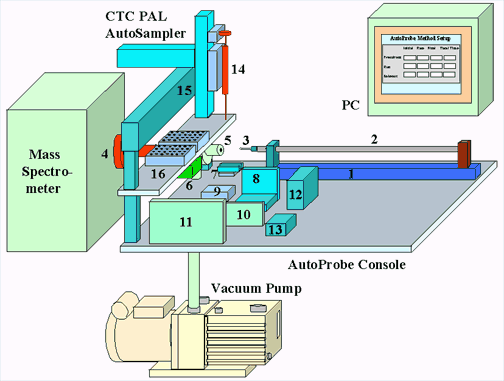
Figure 2 - AutoProbe System Components
- Linear Thrust Column
- Probe Rod
- DEP Probe Tip
- MS Probe Interface
- Isolation Valve Assembly
- Electronic Vacuum Gauge Pressure Sensor
- Isolation Valve Relay Switches
- Filament Current Controller
- Relay
- CTC Power Supply
- AutoProbe Microprocessor Controller
- Servo Controller for Linear Thrust Column
- Electronic Manifold
- Autosampler Syringe
- CTC PAL column

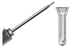
Figure 3 - AP2000 AutoProbe DEP Probe Tip (Plug in Replaceable Tips)
The Direct Exposure Probe (DEP) uses a platinum wire on the end of a probe for the analysis of samples. Samples for analysis are dissolved in a suitable solvent and 0.125 to 1.0 ul of the prepared sample solution is injected onto a small platinum wire loop on the tip of the probe. After the probe has been inserted into the mass spec source, the platinum wire is heated with a small current to desorb the sample into the mass spec source for analysis. This DEP probe filament can be set to a constant current or can be programmed in up to three ramp steps. This versatility of analysis enables the user to optimize the analysis depending on the sample being analyzed.
The DEP or DCI technique is used for the analysis of samples that are
not volatile enough to be introduced into the mass spectrometer via a
GC and therefore must be directly introduced into the mass
spectrometer source. This technique is known as a 'soft' ionization
technique in which thermally labile samples can be ionized with less
fragmentation compared to conventional EI (Electron Impact) mass spec
analysis. A typical DEP analysis can be completed in 1 to 3 minutes.
However, the technique is normally used for single component samples
since minimal separation of samples is possible with this technique
and samples with 2 or more components may be difficult to
interpret.
Frequently DEP sample analysis is performed
utilizing CI (Chemical Ionization) mass spectrometer techniques, which
produces less fragmentation in the mass spectrometer. Due to the
increased abundance of a molecular ion and reduced fragmentation in
the CI techniques, it is possible to analyze and interpret mixtures of
two or more compounds in a sample with this technique.
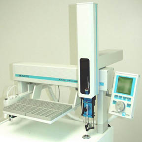
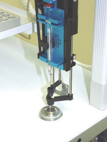
Figure 4 - Injection of Sample onto the DEP Probe via
the CTC Autosampler syringe
A CTC PAL Autosampler is interfaced to the AutoProbe. A wide range of sample trays can be fitted to the CTC PAL Autosampler from which the samples can be loaded onto the DEP probe wire via a syringe. The system permits the cleaning of the syringe between samples. The system also permits the accurate and reproducible delivery of 0.125 to 1.0 ul samples onto the DEP Probe wire.
The AutoProbe adds the dimension of automatic sample loading and unattended analysis to the DEP probe technique. Samples can be analyzed at the rate of 2.0 to 5.0 minutes per sample. Sample analysis time can vary, but a typical sample analysis time is composed of the steps listed below:
1. Position Probe for Sample Loading 15 seconds
2. Load Sample onto Probe Tip 30 seconds
3. Solvent Removal 10 seconds
4. Take probe through isolation valve and into MS source 35 seconds
5. DEP analysis of sample 45 seconds
6. Clean Probe tip with high temperature bakeout 15 seconds
7. Return Probe to position for next sample analysis 30 seconds
TOTAL ANALYSIS TIME 180 seconds (3.0 minutes)
The above typical analysis above requires 3 minutes per sample. However several of the steps can be increased or decreased, depending on the samples being analyzed.
src="../../art/autoprob/ap2000instconf.png">
Figure 5 - Thermo Finnigan Xcalibur Instrument Configuration Window
The AutoProbe is software controlled and fully integrated within the Thermo Finnigan
Xcalibur MS software. The AutoProbe is set up in Xcalibur as an accessory instrument in the Instrumentation Configuration Window. The method parameters for the operation of the AutoProbe, including ramp rates and times of other system parameters, are entered into data screens controlled within the Xcalibur system software.
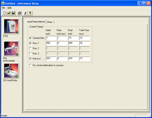
Figure 5 - AutoProbe Method Setup Window for entering probe operational parameters
AutoProbe samples for analysis are placed into sample vial blocks on the CTC PAL Autosampler (Figure 4). A syringe picks up the sample and delivers it to the injection area on the Autoprobe console top. The syringe then injects the sample onto the wire loop at the end of the DEP probe tip.
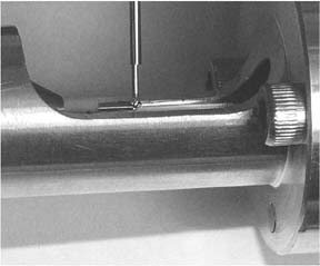
Figure 6 - Injection of sample onto the DEP wire coil
The standard sequence of operation of the AutoProbe system is as follows.
1. Samples are prepared in solution in a concentration range between 1 ng/ul and 1000
ng/ul.
2. The operator sets up a sequence of samples, methods, and processing actions in Xcalibur and starts a run.
3. The Xcalibur software signals the AutoProbe, CTC PAL Autosampler, and MS to prepare for an analysis.
4. The DEP probe moves to the load position.
5. Xcalibur signals the CTC PAL Autosampler to begin a sample run by loading a selected sample.
6. Between 0.125 ul and 1.0 ul of sample are injected onto the DEP filament wire.
7. After the sample is injected onto the DEP filament, the solvent is evaporated from the sample in air. (Alternately, the solvent may be evaporated later inside the vacuum or not at all.)
8. The probe moves to the first vacuum seal, and the electric solenoid valve opens to evacuate the probe inlet.
9. After the vacuum reaches 200 millitorr (adjustable), the probe moves to the second vacuum seal, and the pneumatically controlled ball valve opens. (If a leak occurs, the sequence is paused, the AutoProbe resets itself, and an error is recorded on the log window.)
10. The probe moves to its final position against the MS source. The MS is signaled to begin scanning just before this position is reached.
11. The Xcalibur software downloads the DEP filament current values to the AutoProbe controller and the filament begins its temperature ramp. (The AutoProbe can do up to three filament ramps.)
12. The MS stops scanning and collecting data once the filament ramps are complete.
13. The probe moves away from the MS source about 1" and does an optional filament bakeout to clean the DEP wire and prepare for the next sample.
14. After bakeout, the probe moves to the second seal in the isolation valve, the pneumatic ball valve closes, and the electric solenoid closes.
15. The probe returns to its home position and waits for the signal for the next sample.
Sample Analysis
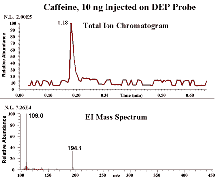
Figure 7 - AutoProbe Analysis of Caffeine Sample (AP1000 on the TRACE MS)

