- ▶
- Heaters/Source
- ▶
- Agilent Heaters and SensorsMass Spectrometry, Scientific Supplies & ManufacturingScientific Instrument Services 5973 Source Heater Tamper Resistant Allen Wrench 5973/5975 Quad Sensor 5985 Source Heater Assembly Agilent Interface Heater Assembly 5971 Interface Heater

- ▶
- Reference Material on InstrumentationArticle - A High Temperature Direct Probe for a Mass Spectrometer Design of a Direct Exposure Probe and Controller for use ona Hewlett-Packard 5989 Mass Spectrometer SIS AP1000 AutoProbe™ SIS AP2000 AutoProbe™ - Description of System HPP7: Direct Probe Electronics Console HPP7: Direct Probe for the Agilent (HP) 5973/5975 MSD HPP7: HP Direct Probe Application Notes HPP7: Installation Directions for the Direct Probe HPP7: Side Cover for the HP 5973 MSD HPP7: Support HPP7: Probe Inlet System for the Agilent (HP) 5973 and 5975 MSD with Automatic Indexed Stops HPP7: Theory of Operation of the Direct Probe and Probe Inlet System Direct Thermal Extraction Thermal Desorption Application Notes Environmental Thermal Desorption Application Notes Food Science Thermal Desorption Application Notes Forensic Thermal Desorption Application Notes GC Cryo-Trap Application Notes Headspace Application Notes Purge & Trap Thermal Desorption Application Notes Theory of Operation of the AutoDesorb® System AutoDesorb Notes for SIS Dealers Adsorbent Resin Application Notes Installation of the Short Path Thermal Desorption System on Agilent (HP) and Other GCs Installation of the Short Path Thermal Desorption System on a Varian 3400 GC AutoDesorb® System Development Team Thermal Desorption Applications and Reference Materials Installation of the Short Path Thermal Desorption System - TD5 Part I - Design & Operation of the Short Path ThermalDesorption System Installation Instructions for the Model 951 GC Cryo-Trap on the HP 5890 Series GC Installation Instructions for the Model 961 GC Cryo-Trap on the HP 5890 Series GC Operation of the Model 951/961 GC Cryo-Trap SIS GC Cryo Traps - Theory of Operation NIST/EPA/NIH Mass Spectral Enhancements - 1998 version (NIST98) SIMION 3D Ion Optics Class Mass Spectrometer Source Cleaning Methods MS Tip: Mass Spectrometer Source Cleaning Procedures Mass Spec Source Cleaning Procedures Micro-Mesh® Abrasive Sheets Research Papers Using New Era Syringe Pump Systems EI Positive Ion Spectra for Perfluorokerosene (PFK) Cap Liner Information How do I convert between fluid oz and milliliters? Which bottle material should I choose? Which bottle mouth should I choose? The Bottle Selection Guide CGA Connections for Gas Tanks Chemical Reaction Interface Mass Spectrometry (CRIMS)

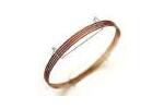
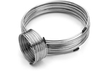
- Instrument Tubing
- ▶
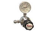
- Gas RegulatorsModel 3530 Series - Single Stage Purity Brass Regulator Model 3510 Series - Single Stage High Purity Stainless Steel Regulators Model 3120 Series - Dual Stage Purity Brass Regulator Model 3810 Series - Dual Stage High Purity Stainless Steel Regulators Tescom Gas Line Regulators 3420 Series Tescom Gas Line Regulators 3450 Series Concoa In-Line Regulators Model 304 Series Concoa In-Line Regulators Model 324 Series
- TD
- GCColumns Fused Silica Tubing Instrument Tubing Injection Port Liners Septa by Manufacturer SIS GC Cryo-Traps Ferrules Valves Swagelok® Fittings Pyrolysis Probe Accessories Gas Generators Gas Regulators Gas Purifiers and Filters Syringes SGE MEPS™-Micro Extraction by Packed Sorbent Purge and Trap System SGE SilFlow™ Stainless Steel Micro-Fluidic Platform Accessories NIST GC RI Library Other GC Supplies Catalog Page D1
- ▶
- GC Cryo-traps
- LiteratureApplication Notes Adsorbent Resins Guide Mass Spec Tips SDS Sheets FAQ MS Calibration Compound Spectra Manuals MS Links/Labs/ Organizations MS Online Tools Flyers on Products/Services Scientific Supplies Catalog About Us NextAdvance Bullet Blender® Homogenizer Protocols Micro-Mesh® Literature Instrumentation Literature Agilent GC/MS Literature SIS News / E-Mail Newsletter NIST MS Database - Update Notifications
- AccessoriesTD Supply Kit Desorption Tubes Adsorbent Resins Desorption Tube Needles Desorption Tube Seals Desorption System Fittings GC Cryo-Trap Extraction Cell TD Sample Loader Prepacked, Conditioned Desorption Tubes Desorption Tube Packing Accessories Stainless Steel Purge Heads Injection Port Liners Tenax TA Poster TD Application Notes Customer Service
- ▶
- Installation Instructions for the Model 951 GC Cryo-Trap on the HP 5890 Series GC (This Page)

Site Preparation
Connecting Liquid C02
The liquid C02 tank must be equipped with an internal eductor (dip) tube to ensure the delivery of liquid C02 rather than gas to the GC Cryo-Trap. DO NOT use a gas regulator on the C02 tank or anywhere in the liquid transfer line to the controller. The liquid is taken from the tank at full pressure. No insulation of the C02 line is required. Use 1/8" stainless steel tubing to transfer the liquid C02 from the tank to the 1/8" fitting on the back of the controller.
Installation of the GC Cryo-Trap on the H.P. 5890 Gas Chromatograph
Schematic of GC Cryo-Trap mounted inside GC Oven.
The GC-Cryo-Trap consists of two components; the Electronics Console and the Cryo-Trap Module. The Electronics Console is designed to sit on top of or in close proximity to the Gas Chromatograph (Fig. 2 and 3). The Cryo-Trap Module is designed to be mounted inside the GC oven just under the front injection port. A mounting bracket is clamped to the bottom of the injection port and the Cryo-Trap is then clamped to the mounting bracket. The only modification to the GC that is required is the removal of the GC injection port cover as explained below.
Figure # 6 - Remove Protective covering over GC injection port inside GC oven.
Step 1
Begin by opening the GC oven door. The mounting bracket is to be mounted just under the injection port (Figure 6). Initial installation can best be accomplished with the GC column removed. However, installation can be accomplished with the column installed provided that extreme care is taken by the installer to avoid breaking the GC column. First, loosen the 2 screws (Figure 6) and remove the protective covering from beneath the injection port (Figure 7).
Figure # 7 - Protective Cover removed from GC injection port.
Install the flat replacement protective cover supplied with the GC Cryo-Trap installation package (#900400) using the same two screws. (Figure 8)
Figure # 8 - Install new flat protective cover on injection port.
Step 2
The Cryo-Trap mounting bracket is designed to clamp to the stem of the GC injection port fitting that attaches to the GC injection port (Figure 9) using the two hex head bolts.
Figure # 9 - Installing mounting bracket to GC injection port.
Step 3
The Cryo-Trap horizontal positions are fixed, since the trap is aligned by the mounting bracket directly under the GC injection port. (Figure 9) To adjust the height of the Cryo-Trap, loosen the two knurled nuts on the Cryo-Trap mounting bracket. (Figure 10) The Cryo-Trap can then be positioned up and down within the Cryo-Trap mounting bracket. This will permit the easy installation and attachment of the capillary columns.
Figure # 10 Adjusting height of GC Cryo-Trap in the mounting bracket
Step 4
Feed the Electrical lead up behind the Cryo-Trap module (Figure 11) and out through one of the exit ports in the GC oven. A convenient GC oven exit to use is the port for a second GC injection port. This second GC injection port exit is preferred due to its close proximity to the Cryo-Trap in the GC oven. Carefully move the insulation in this port to one side, or if preferred remove this plug of insulation for the easy passage of the electrical leads. Other exit ports such as spare detector ports could also be used.
Figure # 11 - Feed electrical leads through GC oven wall.
Figure # 11-b - Installing CO2 line through GC oven wall.
Step 5
Next slide the 1/16" x 0.020" I.D. x 1.0 meter length of stainless steel tubing (part #9512300) through the same hole that the electrical lead exited from the GC oven. Do NOT cut this stainless steel tube or replace it with any other tubing. Its I.D. and length have been factory set to assure optimum operation of the Cryo-Trap. Other diameters or lengths of tubing will not perform the same, resulting in inadequate cooling or causing the Cryo-Trap module to form ice plugs at its exit. Attach the 1/16" nut from this cooling line to the bottom fitting of the Cryo-Trap module. Keep this stainless line and electrical line as short as possible inside the GC oven and position so as not to interfere with the GC column.
Figure # 12 Attaching gas cooling line to GC Cryo-Trap
Use of the exhaust port is optional.
Avoid excess electrical cable hanging in the GC oven. Pass the electrical lead out to the exterior of the GC oven.
NOTE: The pictures show a copper line which is used in the LN2 version. Please follow the written description.
Step 6
Install the GC capillary column in the GC oven. Depending on whether the capillary column itself or a guard column is to be used for trapping in the cryo-trap, insert this capillary column inside the Cryo-Trap module from the bottom. If necessary loosen the Cryo-Trap clamp and slide the Cryo-Trap module upwards to allow more room for inserting the capillary column inside the Cryo-Trap module. If you have difficulty in finding the entrance hole at the bottom of the Cryo-Trap module, the Cryo-Trap module can be removed from the mounting clamp bracket and turned slightly sideways to better view the bottom of the Cryo-Trap module for insertion of the capillary tubing.
Figure # 13 Attaching GC injection port fitting
Step 7
After the capillary column (or guard column) has been inserted through the Cryo-Trap module, attach the GC injection port fitting and appropriate column ferrule (Figure 13). The Cryo-Trap module can be lowered in the Cryo-Trap clamp to better facilitate the attachment of these fittings. It is also advisable to cut the end of the capillary off after the ferrule has been attached to avoid any possibility of ferrule contaminants from entering the column. Then slide the column up into the GC injection port the required distance and tighten the fitting and ferrule to hold the column in place.
Figure # 14 Adjust gap between GC Cryo-Trap and GC injection port nut.
Step 8
When the capillary column has been attached, loosen the Cryo-Trap clamp and slide the Cryo-Trap module up to provide a gap of between 2 to 10 mm between the GC injection port capillary nut and the top of the Cryo-Trap (Figure 14). This will minimize the dead volume between the injection port and the Cryo-Trap module and still maintain a thermal barrier between the injection port and the Cryo-Trap module. Tighten the Cryo-Trap clamp to hold the Cryo-Trap module in place.
Step 9
If a guard column was used, cut the end of the guard column to within 25 mm from the bottom end of the Cryo-Trap module and join this end to the capillary column using an appropriate fitting. When joining most microbore capillary columns to megabore guard columns, the capillary column will slide inside the guard column for 10 to 20 mm to minimize any possibility of active metal surfaces being exposed to the samples being analyzed.
Note: We prefer to use the SGE low dead volume unions for this connection.
Step 10
Tighten all fittings and attach the other end of the column to the detector or Mass Spectrometer.
Electronic Control Connections
Step 11
Attach the lead from the Cryo-Trap module to the connector labeled "Cryo-Trap" on the back of the Cryo-Trap Electronics console and attach the thermocouple to its labeled connector (Figure 15).
Figure # 15 - Back of GC Cryo-Trap Electronics Unit
NOTE: The back panel of the Cryo-Trap controller has a plug labeled "Remote Start". This allows the switching of the Cryo-Trap between the cool and heat modes from a remote device. The remote start cable #782014 which is included in the installation package can be used for connection to the SIS Short Path Thermal Desorption System or other instrument for remote switching of the Cryo-Trap. If you desire to control the Cryo-Trap from the GC then the "Mode Switching Cable #951500 which is included with the installation kit is utilized. See the section in the rear of this manual on instructions for installation of the Mode Switch Cable.
Step 12
Connect the 1/16" stainless Steel capillary tubing from the Cryo-Trap module to the 1/16" fitting on the back of the Electronics Control (labeled "CO2 Out"). Do NOT cut this stainless steel tube or replace it with any other tubing. Its I.D. and length have been factory set to assure optimum operation of the Cryo-Trap. Other diameters or lengths of tubing will not perform the same, resulting in inadequate cooling or causing the Cryo-Trap to form ice plugs at its exit.
Step 13
Connect the 1/8" stainless steel tubing from your source of liquid C02 to the 1/8" fitting on the back of the Electronics Control (labeled "CO2 In"). A source of liquid C02 with a dip stick to provide liquid C02 to the system should be used with the Cryo-Trap. This tank can be placed up to 50 feet away from the Cryo-Trap.
For instruction on the operation of the GC Cryo-Trap - see the Operating Instructions.