- ▶
- Heaters/Source
- ▶
- Agilent Heaters and SensorsMass Spectrometry, Scientific Supplies & ManufacturingScientific Instrument Services 5973 Source Heater Tamper Resistant Allen Wrench 5973/5975 Quad Sensor 5985 Source Heater Assembly Agilent Interface Heater Assembly 5971 Interface Heater

- ▶
- Reference Material on InstrumentationArticle - A High Temperature Direct Probe for a Mass Spectrometer Design of a Direct Exposure Probe and Controller for use ona Hewlett-Packard 5989 Mass Spectrometer SIS AP1000 AutoProbe™ SIS AP2000 AutoProbe™ - Description of System HPP7: Direct Probe Electronics Console HPP7: Direct Probe for the Agilent (HP) 5973/5975 MSD HPP7: HP Direct Probe Application Notes HPP7: Installation Directions for the Direct Probe HPP7: Side Cover for the HP 5973 MSD HPP7: Support HPP7: Probe Inlet System for the Agilent (HP) 5973 and 5975 MSD with Automatic Indexed Stops HPP7: Theory of Operation of the Direct Probe and Probe Inlet System Direct Thermal Extraction Thermal Desorption Application Notes Environmental Thermal Desorption Application Notes Food Science Thermal Desorption Application Notes Forensic Thermal Desorption Application Notes GC Cryo-Trap Application Notes Headspace Application Notes Purge & Trap Thermal Desorption Application Notes Theory of Operation of the AutoDesorb® System AutoDesorb Notes for SIS Dealers Adsorbent Resin Application Notes Installation of the Short Path Thermal Desorption System on Agilent (HP) and Other GCs Installation of the Short Path Thermal Desorption System on a Varian 3400 GC AutoDesorb® System Development Team Thermal Desorption Applications and Reference Materials Installation of the Short Path Thermal Desorption System - TD5 Part I - Design & Operation of the Short Path ThermalDesorption System Installation Instructions for the Model 951 GC Cryo-Trap on the HP 5890 Series GC Installation Instructions for the Model 961 GC Cryo-Trap on the HP 5890 Series GC Operation of the Model 951/961 GC Cryo-Trap SIS GC Cryo Traps - Theory of Operation NIST/EPA/NIH Mass Spectral Enhancements - 1998 version (NIST98) SIMION 3D Ion Optics Class Mass Spectrometer Source Cleaning Methods MS Tip: Mass Spectrometer Source Cleaning Procedures Mass Spec Source Cleaning Procedures Micro-Mesh® Abrasive Sheets Research Papers Using New Era Syringe Pump Systems EI Positive Ion Spectra for Perfluorokerosene (PFK) Cap Liner Information How do I convert between fluid oz and milliliters? Which bottle material should I choose? Which bottle mouth should I choose? The Bottle Selection Guide CGA Connections for Gas Tanks Chemical Reaction Interface Mass Spectrometry (CRIMS)

- TD
- LiteratureApplication Notes Adsorbent Resins Guide Mass Spec Tips SDS Sheets FAQ MS Calibration Compound Spectra Manuals MS Links/Labs/ Organizations MS Online Tools Flyers on Products/Services Scientific Supplies Catalog About Us NextAdvance Bullet Blender® Homogenizer Protocols Micro-Mesh® Literature Instrumentation Literature Agilent GC/MS Literature SIS News / E-Mail Newsletter NIST MS Database - Update Notifications
- ▶
- Theory of Operation of the AutoDesorb® System (This Page)

Automated Short Path Thermal Desorption System
AutoDesorb System mounted on the Agilent/HP 7890, 6890, 5890 GC or Agilent/HP 5973, 5975, 5977 GC/MS
The AutoDesorb was designed to operate with the Agilent/HP 7890, 6890, 5890 GC or Agilent/HP 5973, 5975, 5977 GC/MS. The AutoDesorb System consists of three components, the AutoDesorb Tower, the AutoDesorb Interface and the AutoDesorb PC Software. A Cryo-Trap accessory is also available.
The AutoDesorb Tower sits on top of the GC injection port of the Agilent/HP 7850, 6850 or 5890 GC, where it is utilized for the direct desorption of both volatile and semi-volatile samples into the GC injection port and column. It is NOT permanently mounted to the GC. It is held in place by gravity and can be lifted up and removed in seconds to restore the GC to its normal operation. The only modification to the GC is the addition of a carrier gas shut-off valve which does not effect the normal operation of the GC. The GC can be returned to its normal operation in seconds. The AutoDesorb System permits the setup and automatic analysis of up to 12 desorption tubes.
AutoDesorb System Components
AutoDesorb Electronics Console. The AutoDesorb Interface is an electronics console that interfaces the AutoDesorb Tower to the PC. It consists of a microprocessor that contains software to control the various states of the thermal desorption process including the control of desorption temperatures, cryo-trap temperatures, carrier gas pressure measurement and the various desorption processes. An RS232 cable interfaces this microprocessor to the PC. A desorption cable interfaces the microprocessor to the AutoDesorb Tower.
AutoDesorb Software. The AutoDesorb system is controlled by a PC Windows program that is integrated with the Agilent ChemStation GC or GC/MS program to control the automatic injection, timed desorption, temperature ramp of heater blocks, control of the GC Cryo-Trap accessory, and remote starting of the GC and Mass Spectrometer. A series of PC windows permit the set up of system parameters as well as the monitoring of the system states. A graphical screen displays the actual states of the various AutoDesorb system operations. The Agilent ChemStation program controls the analysis of single samples or multiple samples using the sequential running mode. Data for each sample is entered into the Agilent ChemStation program and downloaded automatically to the AutoDesorb PC software as each sample is analyzed. A log screen displays the results of each sample analyzed.
Cryo-Trap. A GC Cryo-Trap accessory is normally used with the AutoDesorb System. The Cryo-Trap mounts inside the GC oven at the bottom of the injection port. The Cryo-Trap permits the cryo-focusing or trapping of analytes at the front of the GC column during the thermal desorption process using either liquid nitrogen or liquid CO2. The electronics system automatically detects the presence of the Cryo-Trap and also detects the type of Cryo-Trap (CO2 of LN2). Depending on the type of Cryo-Trap detects the appropriate operational parameters and system limits are automatically loaded into the system software for the control of the Cryo-Trap. With CO2 the Cryo-Trap can be cooled down to -70 degrees C and with LN2 the Cryo-Trap can be cooled down to -180 degrees C. A heater circuit enables the rapid heating of the section of column inside the Cryo-Trap to release the analytes in a narrow focused band at the front of the GC column for further GC separation and analysis. The AutoDesorb software and electronics module controls both the heating and cooling of the Cryo-Trap.
Operation of the AutoDesorb System
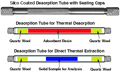
Desorption Tubes and cross section
Samples to be analyzed are collected on Silco® coated Desorption Tubes containing an adsorbent resin such as Tenax® TA or activated carbon. Alternatively, samples of small size (1 to 500 mg) can be packed directly into the desorption tube and subjected to direct thermal extraction. The Silco Coated Stainless Steel Desorption Tubes have an I.D of 3.0 mm or 4.0 mm, are 4.0" long by 1/4" diameter and are threaded on both ends. The inside of the desorption tube is Silco coated to provide and inert environment for the samples during storage or during the actual thermal desorption process. The thermal desorption tubes can be obtained both empty or packed with a wide variety of thermal desorption resins. These thermal desorption tubes can be reused hundreds of times which brings the cost of sample containers down to pennies per sample. Stainless steel tubes with an I.D. of 3.0 mm or 4.0 mm are also available. After pre conditioning the desorption tube and then loading the sample into the desorption tube, the ends of the tubes can be fitted with stainless steel caps with seals to maintain sample integrity during sample storage.
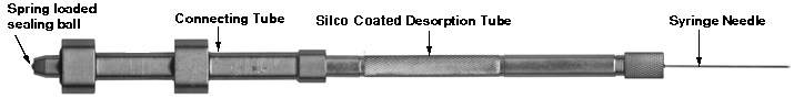
Connecting Tube with Desorption tube and needle attached
When ready for analysis, the thermal desorption tube is attached to a connecting tube and the desorption needle is attached to the other end of the desorption tube. This connecting tube is the adaptor that enables the desorption tube to be attached to the AutoDesorb carousel for thermal desorption analysis. The top to the connecting tube contains a spring loaded sealing ball to seal the desorption tube and sample to maintain sample integrity until the actual thermal desorption process begins.
Graphic of AutoDesorb System (from AutoDesorb System Software Screen)
The thermal desorption tube is then loaded to the AutoDesorb system carousel. Up to 12 desorption tubes can be loaded into the carousel. Tubes can be continuously loaded and unloaded during the running of the sample sequence. During the thermal desorption process, each desorption tube is checked for leaks. If a problem occurs with the sample such as a pressure leak or system parameter problem, the sample is unloaded and resealed and a report of the error is indicated in the sample log table. The sample integrity is maintained, which enables the error to be corrected and the sample reanalyzed.
AutoDesorb System Windows operating within the Agilent ChemStation System
After the sample tube and connecting tube have been placed onto the carousel, the HP ChemStation software is set up with the GC or GC/MS method and the desorption method is setup on the AutoDesorb windows.
When the sample run is initialized on the ChemStation Window, the desorption tube is then loaded into the pickup mechanism. This occurs by a pickup mechanism extending out to meet the desorption tube in the carousel. Next the mechanism picks up the desorption tube. After the tube has been picked up, the arm retracts to position the desorption tube for injection into the GC.
The thermal desorption blocks are preheated to their initial temperature which was set up on the AutoDesorb PC window. As soon as the desorption block temperature is stabilized, the cooling gas to the Cryo-Trap is turned on and the Cryo-Trap is cooled to its pre-selected cooling temperature.
After both the desorption block temperature and the Cryo-Trap temperatures are stabilized, the carrier gas through the desorption tube is turned on. The flow through the desorption tube can be adjusted via the flow controller on top of the AutoDesorb tower to between 1.0 mL/min and 120 mL/min. This purge gas will remain on for an initial purge time which has been previously selected.
AutoDesorb System Status Window
The entire desorption process can be monitored by the AutoDesorb window on the PC. This window displays both graphically and digitally the status of the system including the desorption block temperature, the Cryo-Trap temperature, the time of desorption, the desorption tube pressure, the status of the Purge gas valve as well as the sample name and vial number which were downloaded from the ChemStation software.
AutoDesorb System Time Settings Window
An additional AutoDesorb Windows display the time status of the desorption system. The times are normally preset before desorption is started but can be changed on this window while the system is running. Values for the purge gas time, injection time, desorption time, cryo heat delay, cryo heat time and the GC start time are set on this screen. A vertical black bar (not shown on this screen) displays the current time status of the thermal desorption process.
AutoDesorb System Time Settings Window
Another AutoDesorb PC window displays the thermal desorption and cryo trap temperatures. These values are normally preset before the desorption process is started, but can be changed during a desorption run. The desorption block initial temperature, ramp rate (up to 100 degrees per minute) and final desorption temperature are set on this screen. Up to 3 stages of desorption block heater ramping and temperature holding can be set up to control the heating of the desorption blocks in order to desorb the analytes from the desorption tube into the GC injection port. The Cryo-Trap mode (CO2, LN2 or None) as well as the Cryo-Trap cooling and heating temperatures are set on this screen. A vertical black bar displays (not shown on this screen) the current temperature status of the desorption blocks and cryo-trap at the current time.
After the purge gas has been on for the pre-selected time interval, the thermal desorption tube is injected into the GC injection port. The desorption tube will pass through the opening in the middle plate of the desorption unit base to position the desorption tube in proper alignment with the GC injection port and the normally open desorption block heater assembly. After the injection is complete, a time delay permits the injection port pressure to equilibrate and the system is checked for pressure leaks. If any leaks are detected, the sample is unloaded, the error reported on the sample log table and the next sample in the sequence is analyzed.
If there are no leaks detected, the desorption blocks close around the desorption tube and the desorption tube will balistically heat up to the set temperature or the desorption block temperature program will begin. The combination of the heat applied to the desorption tube and the carrier gas flow through the desorption tube will purge the desired analytes into the GC injection port and onto the front of the GC column. The various parameters are set and utilized according to the application requirements. Normally desorption temperatures between 70 degrees C and 250 degrees C are suitable for most applications. The maximum desorption temperature permissible with the system is 450 degrees C. The heater blocks can be temperature programmed at ramp rates up to 100 degrees/min via a multi-step block heating program. Normal desorption times vary from 3 minutes to 15 minutes, however longer desorption times up to 100 minutes are possible. This permits the trapped samples to be heated by the desorption tube heater blocks, the analytes desorbed from the adsorbent resin and injected directly into the injection port of the gas chromatograph via the shortest path possible, i.e direct injection into the GC much like a syringe.
During the desorption process, the analytes are trapped at the front of the GC column in the Cryo-Trap. The Cryo-Trap temperatures can be set down to -70 degrees C using liquid CO2 or down to -180 degrees C using liquid nitrogen. Since the column inside the Cryo-Trap is maintained at sub-ambient temperatures, the desorbed compounds of interest are trapped on the front of the GC column in a narrow band. Despite the long desorption times, the peaks eluted from the column are extremely sharp and well resolved when the analytes are released.
When the desorption time has finished and the sample has been fully desorbed into the GC column, the desorption blocks open up, the desorption tube heater blocks are turned off and the desorption tube is uninjected from the GC injection port. The Cryo-Trap is rapidly heated to its preset heating temperature to release the analytes from the Cryo-Trap and the GC program is started by the AutoDesorb system. The GC temperature programming is commenced to elute and separate the analytes into the desired components.
The purge gas remains on for an additional 5 minutes to cool the desorption tube, after which time the desorption tube is unloaded back to the AutoDesorb carousel. After a preset time the Cryo-Trap is turned off and allowed to cool.
When the GC analysis is complete, the next sample of the ChemStation sequence is loaded, the GC and AutoDesorb system parameters are reset and this next sample is analyzed.