- ▶
- Heaters/Source
- ▶
- Agilent Heaters and SensorsMass Spectrometry, Scientific Supplies & ManufacturingScientific Instrument Services 5973 Source Heater Tamper Resistant Allen Wrench 5973/5975 Quad Sensor 5985 Source Heater Assembly Agilent Interface Heater Assembly 5971 Interface Heater

- ▶
- Reference Material on InstrumentationArticle - A High Temperature Direct Probe for a Mass Spectrometer Design of a Direct Exposure Probe and Controller for use ona Hewlett-Packard 5989 Mass Spectrometer SIS AP1000 AutoProbe™ SIS AP2000 AutoProbe™ - Description of System HPP7: Direct Probe Electronics Console HPP7: Direct Probe for the Agilent (HP) 5973/5975 MSD HPP7: HP Direct Probe Application Notes HPP7: Installation Directions for the Direct Probe HPP7: Side Cover for the HP 5973 MSD HPP7: Support HPP7: Probe Inlet System for the Agilent (HP) 5973 and 5975 MSD with Automatic Indexed Stops HPP7: Theory of Operation of the Direct Probe and Probe Inlet System Direct Thermal Extraction Thermal Desorption Application Notes Environmental Thermal Desorption Application Notes Food Science Thermal Desorption Application Notes Forensic Thermal Desorption Application Notes GC Cryo-Trap Application Notes Headspace Application Notes Purge & Trap Thermal Desorption Application Notes Theory of Operation of the AutoDesorb® System AutoDesorb Notes for SIS Dealers Adsorbent Resin Application Notes Installation of the Short Path Thermal Desorption System on Agilent (HP) and Other GCs Installation of the Short Path Thermal Desorption System on a Varian 3400 GC AutoDesorb® System Development Team Thermal Desorption Applications and Reference Materials Installation of the Short Path Thermal Desorption System - TD5 Part I - Design & Operation of the Short Path ThermalDesorption System Installation Instructions for the Model 951 GC Cryo-Trap on the HP 5890 Series GC Installation Instructions for the Model 961 GC Cryo-Trap on the HP 5890 Series GC Operation of the Model 951/961 GC Cryo-Trap SIS GC Cryo Traps - Theory of Operation NIST/EPA/NIH Mass Spectral Enhancements - 1998 version (NIST98) SIMION 3D Ion Optics Class Mass Spectrometer Source Cleaning Methods MS Tip: Mass Spectrometer Source Cleaning Procedures Mass Spec Source Cleaning Procedures Micro-Mesh® Abrasive Sheets Research Papers Using New Era Syringe Pump Systems EI Positive Ion Spectra for Perfluorokerosene (PFK) Cap Liner Information How do I convert between fluid oz and milliliters? Which bottle material should I choose? Which bottle mouth should I choose? The Bottle Selection Guide CGA Connections for Gas Tanks Chemical Reaction Interface Mass Spectrometry (CRIMS)

- VacuumPumps Oils/Greases Gauge & Tubes Hose & Accessories Filters - Oil/Charcoal Foreline Traps Gaskets & Material Fittings O-Rings Pump Parts (Precision Plus) Quality Monitor System Distillation Control Acoustic Enclosures For Rotary Vane Pumps Other Vacuum Accessories Digital Vacuum pressure regulator (VPC) Catalog Page F1
- ▶
- Other Vacuum AccessoriesGreenwood Containers Rietschle Vacuum Pump Filters Thermo/Finnigan MAT Incos 50B Vacuum Measurement System 5 Gallon Drum Pump Inland Acidity Test For Vacuum Pump Fluids SIS Replacement Charcoal Filter Element SIS Coalescing Filter Replacement Element Adjustable Gas Ballast Oil Return Kit for Edwards Pumps
- TD
- ▶
- AccessoriesTD Supply Kit Desorption Tubes Adsorbent Resins Desorption Tube Needles Desorption Tube Seals Desorption System Fittings GC Cryo-Trap Extraction Cell TD Sample Loader Prepacked, Conditioned Desorption Tubes Desorption Tube Packing Accessories Stainless Steel Purge Heads Injection Port Liners Tenax TA Poster TD Application Notes Customer Service

- LiteratureApplication Notes Adsorbent Resins Guide Mass Spec Tips SDS Sheets FAQ MS Calibration Compound Spectra Manuals MS Links/Labs/ Organizations MS Online Tools Flyers on Products/Services Scientific Supplies Catalog About Us NextAdvance Bullet Blender® Homogenizer Protocols Micro-Mesh® Literature Instrumentation Literature Agilent GC/MS Literature SIS News / E-Mail Newsletter NIST MS Database - Update Notifications
- ▶
- Thermal Desorption Applications and Reference MaterialsDirect Thermal Extraction Headspace Environmental Food Science Applications Pharmaceuticals Forensic Note 103: EPA Method 325B, Novel Thermal Desorption Instrument Modification to Improve Sensitivity Note 102: Identification of Contaminants in Powdered Beverages by Direct Extraction Thermal Desorption GC/MS Note 101: Identification of Contaminants in Powdered Foods by Direct Extraction Thermal Desorption GC/MS Note 100: Volatile and Semi-Volatile Profile Comparison of Whole Versus Cracked Versus Dry Homogenized Barley Grains by Direct Thermal Extraction Note 99: Volatile and Semi-Volatile Profile Comparison of Whole vs. Dry Homogenized Wheat, Rye and Barley Grains by Direct Thermal Extraction GC/MS Note 98: Flavor and Aroma Profiles of Truffle Oils by Thermal Desorption GC/MS Note 97: Flavor Profiles of Imported and Domestic Beers by Purge & Trap Thermal Desorption GC/MS Note 95: Detection of Explosives on Clothing Material by Direct and AirSampling Thermal Desorption GC/MS Note 94: Detection of Nepetalactone in the Nepeta Cataria Plant by Thermal Desorption GC/MS Note 93: Detection of Benzene in Carbonated Beverages with Purge & Trap Thermal Desorption GC/MS Note 88: Analysis of Silicone Contaminants on Electronic Components by Thermal Desorption GC-MS Note 84: Vacuum Pump Exhaust Filters - Charcoal Exhaust Traps Note 83: Vacuum Pump Exhaust Filters - Oil Mist Eliminators Note 82: Vacuum Pump Exhaust Filters Note 80: Design, Development and Testing of a Microprocessor ControlledAutomated Short Path Thermal Desorption Apparatus Note 79: Volatile Organic Compounds From Electron Beam Cured and Partially Electron Beam Cured Packaging Using Automated Short Path Thermal Desorption Note 77: The Determination of Volatile Organic Compounds in VacuumSystem Components Note 75: An Apparatus for Sampling Volatile Organics From LivePlant Material Using Short Path Thermal Desorption Note 73: The Analysis of Perfumes and their Effect on Indoor Air Pollution Note 71: Flavor Profile Determination of Rice Samples Using Shor tPath Thermal Desorption GC Methods Note 65: Determination of Ethylene by Adsorbent Trapping and Thermal Desorption - Gas Chromatography Note 64: Comparison of Various GC/MS Techniques For the Analysis of Black Pepper (Piper Nigrum) Note 63: Determination of Volatile and Semi-Volatile Organics in Printer Toners Using Thermal Desorption GC Techniques Note 60: Programmable Temperature Ramping of Samples Analyzed ViaDirect Thermal Extraction GC/MS Note 57: Aroma Profiles of Lavandula species Note 55: Seasonal Variation in Flower Volatiles Note 54: Identification of Volatile Organic Compounds in Office Products Note 43: Volatile Organic Composition In Blueberries Note 42: The Influence of Pump Oil Purity on Roughing Pumps Note 41: Hydrocarbon Production in Pine by Direct Thermal Extraction Note 40: Comparison of Septa by Direct Thermal Extraction Note 39: Comparison of Sensitivity Of Headspace GC, Purge and Trap Thermal Desorption and Direct Thermal Extraction Techniques For Volatile Organics Note 38: A New Micro Cryo-Trap For Trapping Of Volatiles At the Front Of a GC Capillary Column Note 37: Volatile Organic Emissions from Automobile Tires Note 36: Identification Of Volatile Organic Compounds In a New Automobile Note 35: Volatile Organics Composition of Cranberries Note 34: Selection Of Thermal Desorption and Cryo-Trap Parameters In the Analysis Of Teas Note 33: Changes in Volatile Organic Composition in Milk Over Time Note 32: Selection and Use of Adsorbent Resins for Purge and Trap Thermal Desorption Applications Note 31: Volatile Organic Composition in Several Cultivars of Peaches Note 30: Comparison Of Cooking Oils By Direct Thermal Extraction and Purge and Trap GC/MS Note 29: Analysis Of Volatile Organics In Oil Base Paints By Automated Headspace Sampling and GC Cryo-Focusing Note 28: Analysis Of Volatile Organics In Latex Paints By Automated Headspace Sampling and GC Cryo-Focusing Note 27: Analysis of Volatile Organics In Soils By Automated Headspace GC Note 26: Volatile Organics Present in Recycled Air Aboard a Commercial Airliner Note 25: Flavor and Aroma in Natural Bee Honey Note 24: Selection of GC Guard Columns For Use With the GC Cryo-Trap Note 23: Frangrance Qualities in Colognes Note 22: Comparison Of Volatile Compounds In Latex Paints Note 21: Detection and Identification Of Volatile and Semi-Volatile Organics In Synthetic Polymers Used In Food and Pharmaceutical Packaging Note 20: Using Direct Thermal Desorption to Assess the Potential Pool of Styrene and 4-Phenylcyclohexene In Latex-Backed Carpets Note 19: A New Programmable Cryo-Cooling/Heating Trap for the Cryo-Focusing of Volatiles and Semi-Volatiles at the Head of GC Capillary Columns Note 18: Determination of Volatile Organic Compounds In Mushrooms Note 17: Identification of Volatile Organics in Wines Over Time Note 16: Analysis of Indoor Air and Sources of Indoor Air Contamination by Thermal Desorption Note 14: Identification of Volatiles and Semi-Volatiles In Carbonated Colas Note 13: Identification and Quantification of Semi-Volatiles In Soil Using Direct Thermal Desorption Note 12: Identification of the Volatile and Semi-Volatile Organics In Chewing Gums By Direct Thermal Desorption Note 11: Flavor/Fragrance Profiles of Instant and Ground Coffees By Short Path Thermal Desorption Note 10: Quantification of Naphthalene In a Contaminated Pharmaceutical Product By Short Path Thermal Desorption Note 9: Methodologies For the Quantification Of Purge and Trap Thermal Desorption and Direct Thermal Desorption Analyses Note 8: Detection of Volatile Organic Compounds In Liquids Utilizing the Short Path Thermal Desorption System Note 7: Chemical Residue Analysis of Pharmaceuticals Using The Short Path Thermal Desorption System Note 6: Direct Thermal Analysis of Plastic Food Wraps Using the Short Path Thermal Desorption System Note 5: Direct Thermal Analysis Using the Short Path Thermal Desorption System Note 4: Direct Analysis of Spices and Coffee Note 3: Indoor Air Pollution Note 2: Detection of Arson Accelerants Using Dynamic Headspace with Tenax® Cartridges Thermal Desorption and Cryofocusing Note 1: Determination of Off-Odors and Other Volatile Organics In Food Packaging Films By Direct Thermal Analysis-GC-MS
- Application NotesNote 103: EPA Method 325B, Novel Thermal Desorption Instrument Modification to Improve Sensitivity Note 102: Identification of Contaminants in Powdered Beverages by Direct Extraction Thermal Desorption GC/MS Note 101: Identification of Contaminants in Powdered Foods by Direct Extraction Thermal Desorption GC/MS Note 100: Volatile and Semi-Volatile Profile Comparison of Whole Versus Cracked Versus Dry Homogenized Barley Grains by Direct Thermal Extraction Note 99: Volatile and Semi-Volatile Profile Comparison of Whole vs. Dry Homogenized Wheat, Rye and Barley Grains by Direct Thermal Extraction GC/MS Note 98: Flavor and Aroma Profiles of Truffle Oils by Thermal Desorption GC/MS Note 97: Flavor Profiles of Imported and Domestic Beers by Purge & Trap Thermal Desorption GC/MS Note 96: Reducing Warping in Mass Spectrometer Filaments, with SISAlloy® Yttria/Rhenium Filaments Note 95: Detection of Explosives on Clothing Material by Direct and AirSampling Thermal Desorption GC/MS Note 94: Detection of Nepetalactone in the Nepeta Cataria Plant by Thermal Desorption GC/MS Note 93: Detection of Benzene in Carbonated Beverages with Purge & Trap Thermal Desorption GC/MS Note 92: Yttria Coated Mass Spectrometer Filaments Note 91: AutoProbe DEP Probe Tip Temperatures Note 90: An Automated MS Direct Probe for use in an Open Access Environment Note 89: Quantitation of Organics via a Mass Spectrometer Automated Direct Probe Note 88: Analysis of Silicone Contaminants on Electronic Components by Thermal Desorption GC-MS Note 87: Design and Development of an Automated Direct Probe for a Mass Spectrometer Note 86: Simulation of a Unique Cylindrical Quadrupole Mass Analyzer Using SIMION 7.0. Note 85: Replacing an Electron Multiplier in the Agilent (HP) 5973 MSD Note 84: Vacuum Pump Exhaust Filters - Charcoal Exhaust Traps Note 83: Vacuum Pump Exhaust Filters - Oil Mist Eliminators Note 82: Vacuum Pump Exhaust Filters Note 81: Rapid Bacterial Chemotaxonomy By DirectProbe/MSD Note 80: Design, Development and Testing of a Microprocessor ControlledAutomated Short Path Thermal Desorption Apparatus Note 79: Volatile Organic Compounds From Electron Beam Cured and Partially Electron Beam Cured Packaging Using Automated Short Path Thermal Desorption Note 78: A New Solution to Eliminate MS Down-Time With No-Tool-Changing of Analytical GC Columns Note 77: The Determination of Volatile Organic Compounds in VacuumSystem Components Note 76: Determination of the Sensitivity of a CRIMS System Note 75: An Apparatus for Sampling Volatile Organics From LivePlant Material Using Short Path Thermal Desorption Note 74: Examination of Source Design in Electrospray-TOF Using SIMION 3D Note 73: The Analysis of Perfumes and their Effect on Indoor Air Pollution Note 72: 1998 Version of the NIST/EPA/NIH Mass Spectral Library, NIST98 Note 71: Flavor Profile Determination of Rice Samples Using Shor tPath Thermal Desorption GC Methods Note 70: Application of SIMION 6.0 To a Study of the Finkelstein Ion Source: Part II Note 69: Application of SIMION 6.0 To a Study of the Finkelstein Ion Source: Part 1 Note 68: Use of a PC Plug-In UV-Vis Spectrometer To Monitor the Plasma Conditions In GC-CRIMS Note 67: Using Chemical Reaction Interface Mass Spectrometry (CRIMS) To Monitor Bacterial Transport In In Situ Bioremediation Note 66: Probe Tip Design For the Optimization of Direct Insertion Probe Performance Note 65: Determination of Ethylene by Adsorbent Trapping and Thermal Desorption - Gas Chromatography Note 64: Comparison of Various GC/MS Techniques For the Analysis of Black Pepper (Piper Nigrum) Note 63: Determination of Volatile and Semi-Volatile Organics in Printer Toners Using Thermal Desorption GC Techniques Note 62: Analysis of Polymer Samples Using a Direct Insertion Probe and EI Ionization Note 61: Analysis of Sugars Via a New DEP Probe Tip For Use With theDirect Probe On the HP5973 MSD Note 60: Programmable Temperature Ramping of Samples Analyzed ViaDirect Thermal Extraction GC/MS Note 59: Computer Modeling of a TOF Reflectron With Gridless Reflector Using SIMION 3D Note 58: Direct Probe Analysis and Identification of Multicomponent Pharmaceutical Samples via Electron Impact MS Note 57: Aroma Profiles of Lavandula species Note 56: Mass Spec Maintenance & Cleaning Utilizing Micro-Mesh® Abrasive Sheets Note 55: Seasonal Variation in Flower Volatiles Note 54: Identification of Volatile Organic Compounds in Office Products Note 53: SIMION 3D v6.0 Ion Optics Simulation Software Note 52: Computer Modeling of Ion Optics in Time-of-Flight mass Spectrometry Using SIMION 3D Note 51: Development and Characterization of a New Chemical Reaction Interface for the Detection of Nonradioisotopically Labeled Analytes Using Mass Spectrometry (CRIMS) Note 50: The Analysis of Multiple Component Drug Samples Using a Direct Probe Interfaced to the HP 5973 MSD Note 49: Analysis of Cocaine Utilizing a New Direct Insertion Probe on a Hewlett Packard 5973 MSD Note 48: Demonstration of Sensitivity Levels For the Detection of Caffeine Using a New Direct Probe and Inlet for the HP 5973 MSD Note 47: The Application Of SIMION 6.0 To Problems In Time-of-Flight Mass Spectrometry Note 46: Delayed Extraction and Laser Desorption: Time-lag Focusing and Beyond Note 45: Application of SIMION 6.0 to Filament Design for Mass Spectrometer Ionization Sources Note 44: The Design Of a New Direct Probe Inlet For a Mass Spectrometer Note 43: Volatile Organic Composition In Blueberries Note 42: The Influence of Pump Oil Purity on Roughing Pumps Note 41: Hydrocarbon Production in Pine by Direct Thermal Extraction Note 40: Comparison of Septa by Direct Thermal Extraction Note 39: Comparison of Sensitivity Of Headspace GC, Purge and Trap Thermal Desorption and Direct Thermal Extraction Techniques For Volatile Organics Note 38: A New Micro Cryo-Trap For Trapping Of Volatiles At the Front Of a GC Capillary Column Note 37: Volatile Organic Emissions from Automobile Tires Note 36: Identification Of Volatile Organic Compounds In a New Automobile Note 35: Volatile Organics Composition of Cranberries Note 34: Selection Of Thermal Desorption and Cryo-Trap Parameters In the Analysis Of Teas Note 33: Changes in Volatile Organic Composition in Milk Over Time Note 32: Selection and Use of Adsorbent Resins for Purge and Trap Thermal Desorption Applications Note 31: Volatile Organic Composition in Several Cultivars of Peaches Note 30: Comparison Of Cooking Oils By Direct Thermal Extraction and Purge and Trap GC/MS Note 29: Analysis Of Volatile Organics In Oil Base Paints By Automated Headspace Sampling and GC Cryo-Focusing Note 28: Analysis Of Volatile Organics In Latex Paints By Automated Headspace Sampling and GC Cryo-Focusing Note 27: Analysis of Volatile Organics In Soils By Automated Headspace GC Note 26: Volatile Organics Present in Recycled Air Aboard a Commercial Airliner Note 25: Flavor and Aroma in Natural Bee Honey Note 24: Selection of GC Guard Columns For Use With the GC Cryo-Trap Note 23: Frangrance Qualities in Colognes Note 22: Comparison Of Volatile Compounds In Latex Paints Note 21: Detection and Identification Of Volatile and Semi-Volatile Organics In Synthetic Polymers Used In Food and Pharmaceutical Packaging Note 20: Using Direct Thermal Desorption to Assess the Potential Pool of Styrene and 4-Phenylcyclohexene In Latex-Backed Carpets Note 19: A New Programmable Cryo-Cooling/Heating Trap for the Cryo-Focusing of Volatiles and Semi-Volatiles at the Head of GC Capillary Columns Note 18: Determination of Volatile Organic Compounds In Mushrooms Note 17: Identification of Volatile Organics in Wines Over Time Note 16: Analysis of Indoor Air and Sources of Indoor Air Contamination by Thermal Desorption Note 14: Identification of Volatiles and Semi-Volatiles In Carbonated Colas Note 13: Identification and Quantification of Semi-Volatiles In Soil Using Direct Thermal Desorption Note 12: Identification of the Volatile and Semi-Volatile Organics In Chewing Gums By Direct Thermal Desorption Note 11: Flavor/Fragrance Profiles of Instant and Ground Coffees By Short Path Thermal Desorption Note 10: Quantification of Naphthalene In a Contaminated Pharmaceutical Product By Short Path Thermal Desorption Note 9: Methodologies For the Quantification Of Purge and Trap Thermal Desorption and Direct Thermal Desorption Analyses Note 8: Detection of Volatile Organic Compounds In Liquids Utilizing the Short Path Thermal Desorption System Note 7: Chemical Residue Analysis of Pharmaceuticals Using The Short Path Thermal Desorption System Note 6: Direct Thermal Analysis of Plastic Food Wraps Using the Short Path Thermal Desorption System Note 5: Direct Thermal Analysis Using the Short Path Thermal Desorption System Note 4: Direct Analysis of Spices and Coffee Note 3: Indoor Air Pollution Note 2: Detection of Arson Accelerants Using Dynamic Headspace with Tenax® Cartridges Thermal Desorption and Cryofocusing Note 1: Determination of Off-Odors and Other Volatile Organics In Food Packaging Films By Direct Thermal Analysis-GC-MS Tech No. "A" Note 14: Elimination of "Memory" Peaks in Thermal Desorption Improving Sensitivity in the H.P. 5971 MSD and Other Mass Spectrometers - Part I of II Improving Sensitivity in the H.P. 5971 MSD and Other Mass Spectrometers- Part II of II Adsorbent Resins Guide Development and Field Tests of an Automated Pyrolysis Insert for Gas Chromatography. Hydrocarbon Production in Pine by Direct Thermal Extraction A New Micro Cryo-Trap for the Trapping of Volatiles at the Front of a GC Capillary (019P) - Comparison of Septa by Direct Thermal Extraction Volatile Organic Composition in Blueberry Identification of Volatile Organic Compounds in Office Products Detection and Indentification of Volatiles in Oil Base Paintsby Headspace GC with On Column Cryo-Trapping Evaluation of Septa Using a Direct Thermal Extraction Technique INFLUENCE OF STORAGE ON BLUEBERRY VOLATILES Selection of Thermal Desorption and Cryo-Trap Parameters in the Analysis of Teas Redesign and Performance of a Diffusion Based Solvent Removal Interface for LC/MS The Design of a New Direct Probe Inlet for a Mass Spectrometer Analytes Using Mass Spectrometry (CRIMS) Application of SIMION 6.0 to Filament Design for Mass Spectrometer Ionization Sources A Student Guide for SIMION Modeling Software Application of SIMION 6.0 to Problems in Time-of-flight Mass Spectrometry Comparison of Sensitivity of Headspace GC, Purge and TrapThermal Desorption and Direct Thermal Extraction Techniques forVolatile Organics The Influence of Pump Oil Purity on Roughing Pumps Analysis of Motor Oils Using Thermal Desorption-Gas Chromatography-Mass Spectrometry IDENTIFICATION OF VOLATILE ORGANIC COMPOUNDS IN PAPER PRODUCTS Computer Modeling of Ion Optics in Time-of-Flight mass Spectrometry using SIMION 3D Seasonal Variation in Flower Volatiles Development of and Automated Microprocessor Controlled Gas chromatograph Fraction Collector / Olfactometer Delayed Extraction and Laser Desorption: Time-lag Focusing and Beyond A New Micro Cryo-Trap for the Trapping of Volatiles at the Front of a GC Column Design of a Microprocessor Controlled Short Path Thermal Desorption Autosampler Computer Modeling of Ion Optics in Time-of-Flight Mass Spectrometry Using SIMION 3D Thermal Desorption Instrumentation for Characterization of Odors and Flavors
- ▶
- Note 83: Vacuum Pump Exhaust Filters - Oil Mist Eliminators (This Page)

Part II - Oil Mist Eliminators
By John J. Manura, Scientific Instrument Services, Ringoes, NJ6/20/00
INTRODUCTION
Vacuum pumps are used on a variety of scientific instruments and can be a major source of laboratory air contamination. When the vacuum pumps are first turned on or when the vacuum pump gas ballast valve is used, a large volume of air is pumped through the pump oil. This results in a fine mist of oil to be emitted from the pump exhaust and into the laboratory air. This mist contains not only oil, but also contains other organic chemicals that are dissolved in the pump oil. When the vacuum pumps are used in instruments such as mass spectrometers, residual organics analyzed by the mass spectrometer end up being trapped in the vacuum pump oil. Eventually these organics are purged out of the oil and into the laboratory air via the vacuum pump exhaust port. These organic chemicals trapped in the oil can be quite toxic or carcinogenic. This is a serious environmental health problem in the laboratory. For this reason, it is normally recommended that vacuum pumps be vented outside the room or to a laboratory exhaust hood. However this is not always practical when the instrumentation is located within the interior of a building. Vacuum pump exhaust filters have been designed to solve this problem.
This is the second in a series of articles on vacuum pump exhaust filtering (1,2 & 3) that describes the use and effectiveness of vacuum pump exhaust filters. This article describes the design of the oil mist eliminator and studies its effectiveness. The oil mist eliminator was designed to trap the heavy oils from the pump oil mist and return them to the vacuum pump. This article will demonstrate the effectiveness of the oil mist eliminator under normal use as well as when the gas ballast valve is used to purge the pump oil.
The oil mist eliminator is not designed for the trapping of volatile organics exhausted by the vacuum pump. A charcoal trap (described in part 3 of this article series) can be used to trap a wide range of the volatile and semi-volatile organics in the vacuum pump exhaust. The oil mist eliminator can be used in conjunction with a charcoal trap to provide for efficient and safe trapping of emissions from laboratory vacuum pumps and can improve the quality of air in the instrumentation laboratory. This two stage trapping system for vacuum pump exhaust is discussed in the first article in this series (1).
EXPERIMENTAL
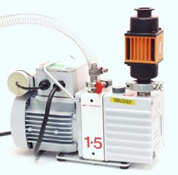
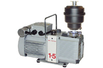
Figure # 1 Vacuum Pump Exhaust Filtering System
The oil mist eliminator mounted on a vacuum pump is shown above (Figure # 1). For these studies, an Alcatel oil mist eliminator (Scientific Instrument Services part # 66827) was used. An NW25 vacuum pump exhaust fitting was first attached to the exhaust port of the vacuum pump, and the Oil Mist Eliminator was clamped to this fitting using a centering ring and clamp.
All studies were performed on a BOC Edwards E2M1.5 rotary vacuum pump, which is the standard model used on the Agilent mass spectrometers. The old oil in the pump was drained and the pump was charged with a volume of Inland 45 pump oil (Scientific Instrument Services). Inland 45 pump oil is the vacuum pump oil of choice because it is a highly refined oil comprised of aliphatic hydrocarbons with chain lengths of between 20 and 40 carbon units. The pump was run for two hours and the oil drained. The pump was again filled with a full charge of Inland 45 pump oil and run for 2 hours with the gas ballast valve open and then for an additional 2 hours with the gas ballast valve closed before any testing was done. This cleaning and flushing procedure assured that the pump was free of contaminants from the previous use of the vacuum pump. For this study a micro-needle valve was attached to the intake port of the vacuum pump to permit a calibrated flow of air into the vacuum pump. The flow through the needle valve was adjusted to 100 ml/min (or between 0 and 400 ml/min for some studies) and calibrated with a Gilibrator Air Flow Calibration System (Scientific Instrument Services Part # 800844-2).
Figure # 2 Analysis of Vacuum Pump Exhaust in the Two Stage Exhaust Filtering System
For the first study, air samples were collected both before and after the oil mist eliminator. The first level (Stage A) is directly from the pump exhaust and before the oil mist eliminator with no filtering. A second air sample was collected after the oil mist eliminator (Stage 1) and right before the exhaust air would enter the laboratory air.
Figure # 3 Schematic of the SIS AutoDesorb System on a GC/MS System
Thermal Desorption tubes were packed with 100 mg of Tenax® TA and flow conditioned with pure nitrogen at 50 ml/min at 300 degrees C for 3 hours. Air samples were collected from the pump stages onto the Tenax adsorbent traps at a collection rate of 25 ml/min for 20 minutes (500 ml total) using a Gilian LFS-113 Air Sampling Pump (Scientific Instrument Services). The collected samples were analyzed using the SIS Automated Short Path Thermal Desorption System (AutoDesorb Model 2000, Scientific Instrument Services) which is described in previous articles (4) and is shown above (Figure # 3). The desorption tubes were attached to the AutoDesorb system and first purged with 30 ml of helium. The desorption tubes were then desorbed from 100 to 250 degrees C at a rate of 60 degrees per minute and held at 250 degrees for a total desorption time of 6 minutes. The desorbed analytes were trapped on a GC Cryo-Trap (Scientific Instrument Services) which had been pre-cooled to -65 degrees C using liquid CO2.
The AutoDesorb system was attached to an Agilent Technologies 6890 GC for the separation of the analytes and the Agilent 5973 MSD to detect and identify the analytes. The GC column for these studies was an Agilent DB5-MS, 0.25 u film thickness, x 0.25 mm I.D. x 30 meters long. A 6" DB-5, 1.5u film thickness x 0.53 mm I.D. guard column was used at the front of the GC column and inside the Cryo-Trap. When the desorption was complete, the Cryo-Trap was rapidly heated to 250 degrees C. The GC column was held at 40 degrees C for 5 minutes and then temperature programmed to 280 degrees C at 10 degrees per minute. The total GC run time was 29 minutes. The Agilent MSD was operated in the EI mode and scanned from 35 to 450 daltons.
For the studies of the ability of the filters to trap volatiles, 10 ul of gasoline was injected directly into the vacuum pump. Gasoline was selected because it contains a wide range of volatile and semi-volatile organics and would accurately simulate the wide range of chemicals that might be injected into a mass spectrometer.
For the quantitation of the analytes in the samples, a series of dilutions of toluene, ethyl-benzene and m-xylene were prepared in methanol at concentrations from 1000 ng/ul to 1 ng/ul. One micro-liter of each of these standards was injected on a preconditioned tenax adsorbent trap and analyzed under the same conditions described above. A calibration curve was calculated from the data and the quantitative results for each of the samples was determined from this data. For the other analytes present in the samples, the same response factor as that calculated for m-xylene was used.
DISCUSSION
Oil Mist Eliminator
Oil mist eliminators are designed to trap the oil vapors or mists which escape from the vacuum pump during initial pump down, during extended operation or when using the gas ballast valve to purge or outgas the vacuum pump oil. When a vacuum pump is first turned on or when the gas ballast valve on the vacuum pump is opened, this oil mist is easily seen as a fine mist, which enters the laboratory environment. This oil mist contains not only hydrocarbons from the pump oil but also contains many other volatile and semi-volatile organic chemicals which were trapped in the oil. The oil mist eliminator is designed to trap this plume of oil mist vapor and return it to the pump.
Figure # 4 Interior Design of the Edwards (left) and Alcatel (right) Oil Mist Eliminators
The interior construction of the Alcatel and Edwards oil mist eliminators are shown above (Figure # 4). The oil mist eliminator mounts on top of the exhaust port of the vacuum pump using standard NW (or QF) style vacuum fitting (Figures 1 & 2). The oil mist eliminator contains a replaceable paper cartridge inside a plastic filter housing. As the vapor exhaust from the vacuum pump escapes through the center of the oil mist eliminator, it must pass through the paper oil mist element (Figure # 4). The paper wick exposes the oil mist to a large surface area to adsorb the oil vapor and collects the oil in a reservoir in the base of the oil mist eliminator and then eventually returns it to the vacuum pump. After the exhaust from the pump passes through the oil mist eliminator paper element it escapes through the top port of the filter. In most oil mist eliminators, a single element is used. However in the Edwards oil mist eliminator a two element filter is used which is slightly more efficient at trapping analytes.
Figure # 5 Oil Mist Exhaust from a Vacuum Pump without Oil Mist Eliminator as a Function of Intake Gas Flow.
The results of the study shown in Figure # 5, demonstrate the need for the oil mist eliminator. In this study the leak valve on the intake port on the vacuum pump was adjusted to flows from 0 ml/min to 400 ml/min. The exhaust air was sampled at the exhaust port of the vacuum pump (Stage A) for each of these leak flows. Additional exhaust air samples were also taken after the oil mist eliminator (Stage 1). Note that even with no air leak into the vacuum pump, some heavy hydrocarbons were detected (top chromatogram between 50 and 60 minutes). As the air leak rate increased, the amount of material detected increased.
Figure # 6 Mass Spectrum of Hydrocarbons in Pump Exhaust.
The broad peaks observed in the total ion chromatograms above, actually consist of a large number of hydrocarbons, both straight and branched chain, with carbon lengths greater than 20 carbons (Figure # 6). These hydrocarbons originate from the vacuum pump oil (Inland 45).
Figure # 7 - Efficiency of the Oil Mist Eliminator at Removing Hydrocarbons
The effectiveness of the oil mist eliminator is demonstrated in Figure # 7. For this study, the purge leak valve on the vacuum pump inlet was opened and the leak flow was adjusted to 300 ml/minute as in the previous study. At the vacuum pump exhaust port (stage A), a high concentration of high molecular weight hydrocarbons from the vacuum pump oil is exhausted from the pump as shown in the first total ion chromatogram above. When the air was sampled after the oil mist eliminator (second chromatogram above), these high molecular weight organics were trapped by the filter and returned to the pump. They were not exhausted out of the oil mist eliminator. When the gas ballast valve was fully open for the other studies listed below, the exhaust rate was greater than 2,000 ml/min. The oil mist eliminator was still able to effectively trap the oils from the vacuum pump exhaust during this high volume gas purge of the vacuum pump. This study demonstrates that the oil mist eliminators are quite effective at performing the job for which they have been designed, that is trapping the vacuum pump oils and returning them to the vacuum pump.
Figure # 8 Trapping Efficiency of Filter Stages (1.0 ul of gasoline injected into pump)
However, the oil mist eliminators with their paper filters are not effective at trapping the lighter hydrocarbons and organics in the vacuum pump exhaust as shown in the chromatograms in Figure # 8. In this study 1.0 ul of gasoline was injected directly into the vacuum pump and the exhaust air subsequently collected at the exhaust port of the vacuum pump (Stage A) and after the oil mist eliminator (Stage 1) and analyzed as described above. The exhaust from the vacuum pump (top chromatogram - Stage A) as well as the exhaust after the oil mist eliminator (second chromatogram - Stage 1) exhibit high concentrations of the volatile aromatics and hydrocarbons from the gasoline, indicating the ineffectiveness of the oil mist eliminator at trapping these volatile organics. As expected the heavy hydrocarbons from the pump oil are not present in the bottom chromatogram, since they were effectively trapped by the oil mist eliminator.
Figure # 9 Trapping Efficiency of Filter Stages (1.0 ul of gasoline injected into pump)
The data in figure # 9 compares the Alcatel and Edwards oil mist eliminators. For this study the gas ballast was opened fully and the exhaust gas sampled after the oil mist eliminator (Stage 1). In both systems, the oil mist eliminators did an effective job at trapping the heavy hydrocarbons from the pump oil and returning them to the vacuum pump. However the Edwards oil mist eliminator performed somewhat better for the lower boiling chemicals. This was due to the two filter elements in the interior of the trap (Figure # 4). However, the Edwards oil mist eliminator is still not sufficient in itself to trap or remove all the volatile and semivolatile organics from the exhaust of the vacuum pumps. Additional filtering is still required for these more volatile organics.
Figure # 10 Time Study of a Vacuum Pump Under Continuous Operation.
In the next study reported in Figure # 10, 10 ul of Gasoline was injected into the vacuum pump and the exhaust air was sampled at both the exhaust port of the vacuum pump (Stage A) and after the oil mist eliminator (Stage 1). The vacuum pump was run continuously for 72 hours for this study. During this study the leak rate into the vacuum pump was maintained at 100 ml/min during the entire time the vacuum pump was running. Only the exhaust before the oil mist eliminator is shown above because the results after the oil mist eliminator were near identical to the results before the oil mist eliminator, because the oil mist eliminator is not effective in trapping the volatile organics. High levels of the volatile organics continued to be purged out the exhaust for more than 24 hours after first injected, and lower levels continued to be detectable for more than the 72 hours. These results were unexpected. We had assumed that volatile organics trapped in the vacuum pump oils would be exhausted out of the pump oil rather quickly since the pump oil runs quite hot and air or gas is continually purged through the pump oil. However the above study demonstrated that even very volatile organics such as benzene, toluene, hexane and even acetone can remain in the pump oil and continue to be exhausted out of the pump over a period of several days.
Figure # 11 Rate of Exhaust of Volatiles in a Vacuum Pump Under Continuous Operation with Gas Ballast Valve Closed
This rate of exhaust of the volatile aromatics is shown in Figure # 11, in which all the data collected in this study are plotted for 5 aromatics. It is important to realize that venting the vacuum pumps for a short period of time when hazardous materials are analyzed will not be effective in preventing these materials from entering the laboratory environment. The vacuum pumps must be vented externally continuously or a better system such as charcoal traps is needed to trap these more volatile organics.
The next study reported in Figure # 12, demonstrates the effectiveness of using the vacuum pump gas ballast valve to purge or clean the vacuum pump oil. The gas ballast valve is normally located on the top or side of the vacuum pump (Figure # 1). The gas ballast valve is used to allow a stream of air to enter the vacuum pump and flush or purge the vacuum pump oil. The vacuum pump exhaust flow rate will exceed 2000 ml/min in this operation. When using the gas ballast valve, any volatile organics or water can be quickly purged from the vacuum pump oil.
In the study reported in Figure # 12, 10 ul of Gasoline was injected into the vacuum pump. The vacuum pump was run continuously for this study and the gas ballast valve was left fully open during this run time except when the air exhaust samples were taken. When the exhaust air samples were taken, the gas ballast valve was closed and the leak valve was left open at 100 ml/min as in the previous studies. Exhaust air was sampled at both the exhaust port of the vacuum pump (Stage A) and after the oil mist eliminator (Stage 1). Only the exhaust port study is shown below because the results after the oil mist eliminator were near identical.
 >
>
Figure # 12 Time Study of a Vacuum Pump Under Continuous Operation with Gas ballast Valve Open
As demonstrated above (Figure # 12) leaving the gas ballast valve (fully open) for 2 hours is equivalent to permitting the vacuum pump to operate without the gas ballast valve open for 48 hours as was shown in the previous study (Figure # 10). Using the gas ballast valve for 4 to 6 hours is very effective at removing most of the volatile organics trapped in the vacuum pump oil.
Figure # 13 Rate of Exhaust of Volatiles in a Vacuum Pump Under Continuous Operation with Gas Ballast Valve Open .
This rate of exhaust of the volatile aromatics is shown in Figure # 13, in which the all the data collected in this study are plotted for 5 aromatics as was done for the 72 hour study reported above. Using the gas ballast valve for 4 to 5 hours of continuous use will do an effective job of purging the volatile organics from the pump oil. The vacuum pumps must be vented externally continuously or a better system such as charcoal traps is needed to trap these more volatile organics during this operation to prevent these organics from entering the laboratory environment.
Maintenance and Service of the Oil Mist Eliminator
The only service normally required of the oil mist eliminator is the occasional replacement of the paper filter element. This replacement should be performed once a year under normal operations, unless very acidic or corrosive materials are being purged into the vacuum pump. Since the filter is made of a paper composite, these corrosive chemicals can cause the filter element to rapidly erode, in which case the filters should be changed more frequently. The filter can be easily replaced by unbolting the two parts of the filter housing and simply replacing the paper element with a new element.
CONCLUSION
This is Part II of a three part series of articles on the effectiveness of vacuum pump exhaust traps. Part I describes the two stage vacuum pump exhaust filter system for the complete treatment of vacuum pump exhaust (1). Part II describes the operation and the effectiveness of the oil mist eliminator (2). Part III of this series describes the charcoal trap and its effectiveness at removing volatiles and semi-volatiles from vacuum pump exhaust (3)
The oil mist eliminator has been shown to be very effective in preventing oil mists and the heavy vacuum pump oils from being exhausted into the laboratory air. The oil mist eliminator is effective in trapping these high molecular weight components and in returning them to the vacuum pump. However the oil mist eliminator is not effective in trapping the lighter hydrocarbons, aromatics and other volatile organics which can contaminate the pump oil. To trap these materials, another filter called a charcoal trap is used as described in part three of this article series (3).
Volatile and semi-volatile organics are trapped in the vacuum pump oils from the operation of various instruments, and are slowly exhausted from the vacuum pump oil over a period of several days. This process of purging these volatile organics from the vacuum pump oil can be accelerated up by using the vacuum pump gas ballast valve. During the gas ballast operation, it is recommended that the oil mist eliminator be used to prevent the oil mist from being purged out of the vacuum pump and into the laboratory atmosphere. However in this operation, the volatile organics would still be purged into the laboratory air. When the oil mist eliminator is used as part of the two stage vacuum pump filtering system (1), it traps these heavy vacuum pump oils and prevents them from contaminating and saturating the second stage filter.
References
(1) Vacuum Pump Exhaust Filters, Part I Two Stage Vacuum Pump Exhaust Filter System, by John J. Manura, April 2000, SIS Application Note # 82 http://www.sisweb.com/referenc/applnote/app-82.htm
(2) Vacuum Pump Exhaust Filters, Part II Oil Mist Eliminators, by John J. Manura, April 2000, SIS Application Note # 83 http://www.sisweb.com/referenc/applnote/app-83.htm
(3) Vacuum Pump Exhaust Filters, Part III Charcoal Exhaust Traps, by John J. Manura, April 2000, SIS Application Note # 84 http://www.sisweb.com/referenc/applnote/app-84.htm
(4) Design, Development and Testing of a Microprocessor Controlled Automated
(5) AutoDesorb Short Path Thermal Desorption Apparatus, by John J. Manura, Vinod T. Das, Christopher Baker, Daniel Lieske, John C. Miller, John Manos, Roland Roadenbaugh, Thomas G. Hartman, SIS Application Note # 80 http://www.sisweb.com/referenc/applnote/app-80.htm
(6) Two Stage Vacuum Pump Exhaust Filter Systems, Scientific Instrument Services, Ringoes, NJ http://www.sisweb.com/vacuum/sis/exfilter.htm