- ▶
- Heaters/Source
- ▶
- Agilent Heaters and SensorsMass Spectrometry, Scientific Supplies & ManufacturingScientific Instrument Services 5973 Source Heater Tamper Resistant Allen Wrench 5973/5975 Quad Sensor 5985 Source Heater Assembly Agilent Interface Heater Assembly 5971 Interface Heater

- ▶
- Instrument Tubing
- ▶
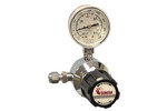
- Gas RegulatorsModel 3530 Series - Single Stage Purity Brass Regulator Model 3510 Series - Single Stage High Purity Stainless Steel Regulators Model 3120 Series - Dual Stage Purity Brass Regulator Model 3810 Series - Dual Stage High Purity Stainless Steel Regulators Tescom Gas Line Regulators 3420 Series Tescom Gas Line Regulators 3450 Series Concoa In-Line Regulators Model 304 Series Concoa In-Line Regulators Model 324 Series
- TD
- ▶
- AccessoriesTD Supply Kit Desorption Tubes Adsorbent Resins Desorption Tube Needles Desorption Tube Seals Desorption System Fittings GC Cryo-Trap Extraction Cell TD Sample Loader Prepacked, Conditioned Desorption Tubes Desorption Tube Packing Accessories Stainless Steel Purge Heads Injection Port Liners Tenax TA Poster TD Application Notes Customer Service
- GCColumns Fused Silica Tubing Instrument Tubing Injection Port Liners Septa by Manufacturer SIS GC Cryo-Traps Ferrules Valves Swagelok® Fittings Pyrolysis Probe Accessories Gas Generators Gas Regulators Gas Purifiers and Filters Syringes SGE MEPS™-Micro Extraction by Packed Sorbent Purge and Trap System SGE SilFlow™ Stainless Steel Micro-Fluidic Platform Accessories NIST GC RI Library Other GC Supplies Catalog Page D1
- ▶
- GC Cryo-traps
- ▶
- SIS 1-Inch Micro Cryo-Trap (Model 971/981) (This Page)

")
New Programmable Micro Cryo-Cooling and Heating Trap for the Cryo-focusing of Volatiles and Semi-volatiles at the Head of GC Capillary Columns.
Features
- Only 1.0" Long - Uses minimum amount of cooling gas
- Reduction of C02 or LN2 use by 97% as compared to cooling the entire oven.
- Improve Chromatographic resolution of early eluting peaks
- Dual programmable cryo-cooling and heating cycles
- Trap compounds in the GC oven at the head of the GC column.
- Remote input connector for switching between cryo-cooling and heating cycle switching via GC, Desorption system or manually.
- Rapid heating up to 400 deg C at > 1000 deg C per minute.
- Remote start output signal for starting GC, MS or recorder.
Applications
- Thermal Desorption Sample Trapping
- Purge and Trap Systems
- GC Headspace Sample Analysis
- Multi-dimensional GC applications
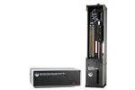
Theory of Operation
 Cryo-trap in GC oven.
 Diagram of cryo-trap.
 Purge & Trap of Black Tea, before and after cryo-trapping.
 Trapping Efficiency of Hydrocarbons on 0.53 mm DB5 (1.5u film thickens) at various
cryo-trapping temperatures 0 to -180 °C.
Trapping Efficiency of Hydrocarbons on 0.53 mm DB5 (1.5u film thickens) at various
cryo-trapping temperatures 0 to -180 °C.
CO2/LN2
New Programmable Micro Cyro-cooling and heating trap for the Cryo-focusing of volatiles and semivolatiles at the head of GC capillary columns.
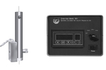
Two models of the Micro Cryo-Trap are now available. The Model 971 is designed for liquid CO2 use only for cryo-trapping temperatures down to -70 °C. The Model 981 is designed for Liquid Nitrogen use only for cryo-trapping temperatures down to-180 °C. Each model can maintain any cooling temperature within +/- 3 °C from its minimum temperature up to room temperature. In order to release the trapped volatiles from the GC Cryo-Traps, both models can heat the GC Cryo-Trap at temperatures up to 400 °C at a heating ramp rate in excess of 1200 deg/minute. Most users prefer to use the C02 version of the GC Cryo-Trap (Model 971) due to the ease of handling liquid C02 and for applications where -70 °C is an acceptable lower temperature limit.
If lower temperatures are required, then the liquid nitrogen version of the GC Cryo-Trap (Model 981) must be used. The liquid nitrogen delivery lines are larger than the CO2 lines and the liquid nitrogen lines must be insulated. This makes installation somewhat more cumbersome. In addition the Liquid Nitrogen version uses more cooling gas and is slightly more audible.
Model 971 Micro Cryo-Trap for use with Liquid C02
The Model 971 Micro Cryo-Trap is designed for use with liquid CO2 tanks with a DIP tube. The minimum temperature of cooling is -70 °C. This model comes with the Micro Cryo-Trap, the dual temperature electronics controller, connecting cables and stainless steel connecting line. *Order installation kit below.
Model 981 Micro Cryo-Trap for use with Liquid Nitrogen
The Model 981 Micro Cryo-Trap is designed for use with liquid nitrogen tanks (low pressure). The minimum temperature of cooling is -180 deg. C. This model comes with the Micro Cryo Trap, the dual temperature electronics controller, connecting cables and copper connecting line. *Order installation kit below.
Installation Kits
Depending on the make and model of your GC, an installation kit must be ordered separately as described below. First you must decide which model of Cryo-Trap is required for your application; the Model 971 for use with C02, or the Model 981 for use with liquid Nitrogen. Although the Cryo-Trap can be used for both CO2 and LN2, the electronics are not interchangeable for the two systems.
You must then select which installation kit is required based on the make and model of your gas chromatograph. Either of the two Micro Cryo-Trap(tm) models will fit the same installation kits listed.
Literature/Installation
References and Literature
- Micro Cryo-Trap Theory of Operation - Description
- Model 971 Operating Manual (CO2)
- Model 981 Operating Manual (LN2)
- Application Note # 38 - A New Micro Cryo-Trap for Trapping of Volatiles at the front of a GC Capillary Column
- Application Note # 19 - Design and Application of the SIS GC Cryo-Trap
- Application Note # 24 - Selection of GC Guard Columns for Use with the GC Cryo-Trap
- Application Note # 28 - Analysis of Volatile Organics in Latex Paints by Automated Headspace Sampling and GC Cryo-Focusing
- Application Note # 29 - Analysis of Volatile Organics in Oil Base Paints by Automated Headspace Sampling and GC Cryo-Focusing
- Application Note # 30 - Comparison of Cooking Oils by Direct Thermal Extraction and Purge and Trap GC/MS
- Application Note # 31 - Volatile Organic Composition in Several Cultivars of Peach by Thermal Desorption with Cryo-Trapping
- Application Note # 34 - Selection of Thermal Desorption and Cryo-Trap Parameters in the Analysis of Teas
- Application Note # 35 - Volatile Organic Composition of Cranberries by Thermal Desorption with Cryo-Trapping
- Application Note # 36 - Identification of Volatile Organic Compounds in a New Automobile by Thermal Desorption with Cryo-Trapping
| Part No. | Description | Stock/ Lead Time |
Price EA |
Order |
|---|---|---|---|---|
| Cryo-Traps | ||||
| 971110 | Model 971 Micro Cryo-Trap, electronics controller, connecting cables, and stainless steel connecting lines, for use with liquid C02 | DISCONTINUED | --- | --- |
| 981110 | Model 981 Micro Cryo-Trap, electronics controller, connecting cables, and stainless steel connecting lines, for use with liquid LN2 | DISCONTINUED | --- | --- |
| Cryo-Traps Install Kits | ||||
| 900110 | Cryo-Trap Install Kit for HP 5890A | 0†Standard lead-time for non-stock items is approximately two weeks depending on the item. | $381.25 | |
| 900111 | Cryo-Trap Install Kit for HP5890 Series I and II | 0†Standard lead-time for non-stock items is approximately two weeks depending on the item. | $301.88 | |
| 900112 | Cryo-Trap Install Kit for Agilent 6890 & Agilent 7890 | 1 | $111.88 | |
| 900120 | Cryo-Trap Install Kit for Varian 3400/3600/3700 with 1075 Split/Splitless Injector, 1040 Megabore Injector, 1041 Universal Injector, 1077 Split/Splitless Capillary Injector | 0†Standard lead-time for non-stock items is approximately two weeks depending on the item. | $152.50 | |
| 900121 | Cryo-Trap Install Kit for Varian 3600 w/ 1078 Injector | 0†Standard lead-time for non-stock items is approximately two weeks depending on the item. | $152.50 | |
| 900122 | Cryo-Trap Install Kit for Varian 3800 | 0†Standard lead-time for non-stock items is approximately two weeks depending on the item. | $217.50 | |
| 900131 | Cryo-Trap Install Kit for Shimadzu GC-2010/2014 | DISCONTINUED | --- | --- |
| 900130 | Cryo-Trap Install Kit for Shimadzu GC-9A | 0†Standard lead-time for non-stock items is approximately two weeks depending on the item. | $155.00 | |
| 900140 | Cryo-Trap Install Kit for Thermo Finnigan GCQ | 0†Standard lead-time for non-stock items is approximately two weeks depending on the item. | $155.00 | |
| 900150 | Cryo-Trap Install Kit for Thermo Finnigan Trace GC | 24 hours‡Lead time for this non-stock item is approximately 24 hours. | $118.75 | |
| 96225001 | Cryo-Trap Body | DISCONTINUED | --- | --- |
| 98225001 | Cryo-Trap Body | DISCONTINUED | --- | --- |
|
* Call for availability. † Standard lead-time for non-stock items is approximately two weeks depending on the item. ‡ Lead time for this non-stock item is approximately 24 hours. | ||||
|
|
||||
 SIS 4-Inch GC Cryo-Trap
 (Model 951/961)
 Short Path Thermal Desorption Accessories Supply Kit