- ▶
- Heaters/Source
- ▶
- Agilent Heaters and SensorsMass Spectrometry, Scientific Supplies & ManufacturingScientific Instrument Services 5973 Source Heater Tamper Resistant Allen Wrench 5973/5975 Quad Sensor 5985 Source Heater Assembly Agilent Interface Heater Assembly 5971 Interface Heater

- ▶
- Probes
- ▶
- AutoProbe - Automated Direct Probe for the Thermo TRACE™ DSQ/PolarisQ™ (This Page)


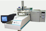
SIS AP2000 attached to the PolarisQ or TRACE DSQ.
New Automated Direct Insertion Probe for the PolarisQ™ and TRACE DSQ™ Mass Spectrometers from Thermo Electron Corp.
Description
The AutoProbe™ System is an Automated Direct Exposure Probe (DEP) for the Finnigan PolarisQ and TRACE DSQ™ Mass Spectrometer systems. The AutoProbe System injects samples directly into the MS source for mass spec sample analysis with no chromatographic separation. This permits samples to be analyzed in 3 minutes or less. The AutoProbe™ operates in the Thermo Finnigan Xcalibur™ MS Software environment and is fully integrated with the Xcalibur™ software, including system setup, methods setup, system operation and data storage. Applications of the direct probe technique include the screening of drug and pharmaceutical samples, quality control sample analysis, spot analysis of chemical reaction mixtures to monitor rates of synthesis, and the analysis of compounds which cannot be chromatographed. The AutoProbe System is used where high volumes of samples need to be analyzed quickly or it can be used in an "Open Access" environment where it can be used by multiple users with minimal MS expertise.
The direct probe was one of the earliest techniques used to introduce
samples into a mass spectrometer. The technique is still popular
today because it provides a means to perform rapid sample analysis
with minimal or no sample preparation. The electron impact (EI) mass
spectrometer mode of operation can be used when the sample to be
analyzed is relatively pure or when chromatographic separation of a
mixture is not required. Direct probe analysis has also been widely
used with Chemical Ionization (CI) mass spectrometry. The simplicity
of the CI spectrum permits the analysis of mixtures, whose spectra are
difficult to interpret using the EI mode of operation.
Applications of the direct probe technique include the screening of
drug and pharmaceutical samples, quality control sample analysis, spot
analysis of chemical reaction mixtures to monitor rates of synthesis,
and the analysis of compounds which cannot be chromatographed. The
AutoProbe System is used where high volumes of samples need to be
analyzed quickly or it can be used in an "Open Access"
environment where it can be used by multiple users with minimal MS
expertise.
The AutoProbe™ console is packaged in a white plastic cabinet which attaches to the MS. The probe rod is attached to a servo linear actuator which serves as the motor to drive the probe through the isolation valve and into the mass spectrometer source. Replaceable DEP probe tips can be plugged into the tip of the probe rod.
Features
-
Automated Direct Probe for continuous analysis of probe samples
-
Can be used in Open Access Mode of Operation
-
Unattended analysis 200 to 500 samples per day
-
MS analysis of samples in 2 to 5 minutes per sample
-
Uses Direct Exposure Probe (DEP) Technique (also called DCI)
-
Uses CTC PAL Autosampler to load liquid samples onto probe tip
-
Long life plug in replaceable probe filaments (expected life > 1000 samples)
-
Long life probe seals (expected life > 2000 injections)
-
Analyze samples at a constant current or program in up to three temperature ramps
-
Automatic cleaning of filament between samples via high temperature bakeout
-
Totally integrated with the Thermo Finnigan Xcalibur software
-
Easy to replace probe seals have expected life in excess of 2000 injections
-
Automatic injection of probe though an automated vacuum lock isolation valve
-
Vacuum gauge in isolation valve eliminates probe from injecting if the system has leaks.
-
Automatic error detection designed into the software
-
Can use different methods for subsequent samples in a series
Specs
| Voltages |
|
|---|---|
| Fuses | Main fuse: 10 amp slow blow |
| Compressed Air |
|
| Dimensions |
|
| Weight |
|
Mass Spectrometer System Requirements
- Finnigan PolarisQ™ or TRACE DSQ™ MS System from Thermo Electron Corp. Contact us about adapting to other MS's.
- A Windows based operating system.
- Finnigan Xcalibur™ Version 1.3 or above software (tested up to 1.4) Can be adapted to Xcalibur 2.x. Finnigan Xcalibur OpenAccess is optional (tested under 1.1 and 1.3).
- PolarisQ or TRACE DSQ MS Source with Ion Volumes modified for the AutoProbe (see parts section E of the manual).
Components
Figure 1 - AutoProbe System Components
- Linear Thrust Column
- Probe Rod
- DEP Probe Tip
- MS Probe Interface
- Isolation Valve Assembly
- Electronic Vacuum Gauge Pressure Sensor
- Isolation Valve Relay Switches
- Filament Current Controller
- Relay
- CTC Power Supply
- AutoProbe Microprocessor Controller
- Servo Controller for Linear Thrust Column
- Electronic Manifold
- Autosampler Syringe
- CTC PAL column
The Panel on the front display has a series of three LED lights which display the status of the AutoProbe - Power On, Running and a Fault indicator. Also on this display is an emergency Pause button which will stop the operation of the AutoProbe from injecting the probe or running the sample, until the switch is pressed a second time to continue the operation of the system. This switch only pauses the AutoProbe - it does not stop or pause the CTC PAL Autosampler.

Figure 2 - Front Panel Display on the AutoProbe
The back panel on the rear of the AutoProbe has a series of plugs for the attachment of the various cables required to interface the AutoProbe to the CTC PAL Autosampler, the PC, and the mass spectrometer. The main Power cord is located here as well as the main power switch and a second switch for the CTC PAL Autosampler.

Figure 3 - Back Panel on the AutoProbe Console
Functions
An pneumatically controlled isolation valve permits the probe to be introduced into the mass spectrometer vacuum system while maintaining a good vacuum in the MS. When the probe is inserted into the first probe seal of the isolation valve, a vacuum valve opens to allow the accessory vacuum pump to evacuate the probe inlet. A vacuum gauge measures this vacuum and when it evacuates down to 200 millitorr, the probe is advanced to the second seal in the probe inlet. A rotary turn pneumatically operated ball valve opens to permit the probe to be inserted through the isolation valve and into the mass spectrometer.

Figure 1 - Isolation Valve Assembly on the AutoProbe
The two drawings below show the insertion of the probe through the isolation valve.

Figure 2 - DEP Probe injected to the First Vacuum Seal (Isolation Valve closed)

Figure 3 - DEP Probe Passing through the Rotary Ball Isolation Valve (Isolation Valve Open)
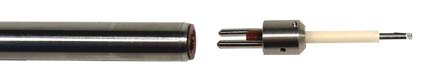
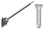
Figure 4 - AP2000 AutoProbe DEP Probe Tip (Plug in Replaceable Tips)
The Direct Exposure Probe (DEP) uses a platinum wire on the end of a probe for the analysis of samples. Samples for analysis are dissolved in a suitable solvent and 0.125 to 1.0 ul of the prepared sample solution is injected onto a small platinum wire loop on the tip of the probe. After the probe has been inserted into the mass spec source, the platinum wire is heated with a small current to desorb the sample into the mass spec source for analysis. This DEP probe filament can be set to a constant current or can be programmed in up to three ramp steps. This versatility of analysis enables the user to optimize the analysis depending on the sample being analyzed.
The DEP or DCI technique is used for the analysis of samples that are
not volatile enough to be introduced into the mass spectrometer via a
GC and therefore must be directly introduced into the mass
spectrometer source. This technique is known as a 'soft' ionization
technique in which thermally labile samples can be ionized with less
fragmentation compared to conventional EI (Electron Impact) mass spec
analysis. A typical DEP analysis can be completed in 1 to 3 minutes.
However, the technique is normally used for single component samples
since minimal separation of samples is possible with this technique
and samples with 2 or more components may be difficult to
interpret.
Frequently DEP sample analysis is performed
utilizing CI (Chemical Ionization) mass spectrometer techniques, which
produces less fragmentation in the mass spectrometer. Due to the
increased abundance of a molecular ion and reduced fragmentation in
the CI techniques, it is possible to analyze and interpret mixtures of
two or more compounds in a sample with this technique.


Figure 5 - Injection of Sample onto the DEP Probe via
the CTC Autosampler syringe
A CTC PAL Autosampler is interfaced to the AutoProbe. A wide range of sample trays can be fitted to the CTC PAL Autosampler from which the samples can be loaded onto the DEP probe wire via a syringe. The system permits the cleaning of the syringe between samples. The system also permits the accurate and reproducible delivery of 0.125 to 1.0 ul samples onto the DEP Probe wire.
The AutoProbe adds the dimension of automatic sample loading and unattended analysis to the DEP probe technique. Samples can be analyzed at the rate of 2.0 to 5.0 minutes per sample. Sample analysis time can vary, but a typical sample analysis time is composed of the steps listed below:
1. Position Probe for Sample Loading 15 seconds
2. Load Sample onto Probe Tip 30 seconds
3. Solvent Removal 10 seconds
4. Take probe through isolation valve and into MS source 35 seconds
5. DEP analysis of sample 45 seconds
6. Clean Probe tip with high temperature bakeout 15 seconds
7. Return Probe to position for next sample analysis 30 seconds
TOTAL ANALYSIS TIME 180 seconds (3.0 minutes)
The above typical analysis above requires 3 minutes per sample. However several of the steps can be increased or decreased, depending on the samples being analyzed.
AutoProbe samples for analysis are placed into sample vial blocks on the CTC PAL Autosampler (Figure 4). A syringe picks up the sample and delivers it to the injection area on the Autoprobe console top. The syringe then injects the sample onto the wire loop at the end of the DEP probe tip.

Figure 6 - Injection of sample onto the DEP wire coil
The standard sequence of operation of the AutoProbe system is as follows.
1. Samples are prepared in solution in a concentration range between 1 ng/ul and 1000
ng/ul.
2. The operator sets up a sequence of samples, methods, and processing actions in Xcalibur and starts a run.
3. The Xcalibur software signals the AutoProbe, CTC PAL Autosampler, and MS to prepare for an analysis.
4. The DEP probe moves to the load position.
5. Xcalibur signals the CTC PAL Autosampler to begin a sample run by loading a selected sample.
6. Between 0.125 ul and 1.0 ul of sample are injected onto the DEP filament wire.
7. After the sample is injected onto the DEP filament, the solvent is evaporated from the sample in air. (Alternately, the solvent may be evaporated later inside the vacuum or not at all.)
8. The probe moves to the first vacuum seal, and the electric solenoid valve opens to evacuate the probe inlet.
9. After the vacuum reaches 200 millitorr (adjustable), the probe moves to the second vacuum seal, and the pneumatically controlled ball valve opens. (If a leak occurs, the sequence is paused, the AutoProbe resets itself, and an error is recorded on the log window.)
10. The probe moves to its final position against the MS source. The MS is signaled to begin scanning just before this position is reached.
11. The Xcalibur software downloads the DEP filament current values to the AutoProbe controller and the filament begins its temperature ramp. (The AutoProbe can do up to three filament ramps.)
12. The MS stops scanning and collecting data once the filament ramps are complete.
13. The probe moves away from the MS source about 1" and does an optional filament bakeout to clean the DEP wire and prepare for the next sample.
14. After bakeout, the probe moves to the second seal in the isolation valve, the pneumatic ball valve closes, and the electric solenoid closes.
15. The probe returns to its home position and waits for the signal for the next sample.
Sample Analysis
Figure 7 - AutoProbe Analysis of Caffeine Sample (AP1000 on the TRACE MS)
The vacuum pump is attached to a pump flange nipple on the bottom of the AutoProbe console. This pump provides for the initial roughing out vacuum of the AutoProbe isolation valve. An electronic vacuum gauge measures this vacuum level to assure that no leaks exist in the probe seals before the probe in taken into the MS source.

Figure 8 - Vacuum Pump provides roughing out vacuum for the AutoProbe isolation valve
Software
The AutoProbe is software controlled and fully integrated within the Thermo Finnigan Xcalibur MS software. The AutoProbe is set up in Xcalibur as an accessory instrument in the Instrumentation Configuration Window. The method parameters for the operation of the AutoProbe, including ramp rates and times of other system parameters, are entered into data screens controlled within the Xcalibur system software.AutoProbe Software and PC Control
The AutoProbe System has four levels of software that control its entire operation. SIS developed software for the first three levels. The four levels include:
(1) Embedded Software - This resides on the embedded C-programmable microprocessor controller inside the AutoProbe instrument. It directly controls the various hardware components of the AutoProbe, including the servo controller for the linear actuator, the DEP filament current controller, the isolation and rough-pump valves, the vacuum gauge sensor, and the pneumatic valves for the ball valve.
(2) PC-based Instrument Control Software - This controls the AutoProbe instrument from the PC. It does this by communicating with the embedded software (1) via a serial communications link. The PC software sends commands (such as sample run requests) to the embedded software and reads back status data such as the filament current, vacuum readings, the probe position, and operating states. C++, wxWindows, and COM technologies were used. CTC developed their own software for controlling the autosampler. In a typical operation, this layer of software is transparent to the user.
(3) Virtual Instrument Modules - Each instrument of the AutoProbe System is associated with a plug-in module called an "Xcalibur virtual instrument (VI)." These virtual instruments allow instrument vendors to integrate their own instrument control software (2) into the Thermo Finnigan Xcalibur software package (4). Virtual instruments can be thought of as (software) abstractions of instrument hardware. They conform to various standards such as how instruments are configured, methods are set up, and instrument operations are synchronized. Therefore, the entire AutoProbe system is seamlessly integrated into Xcalibur according to the Xcalibur instrument model. SIS developed a VI for the AutoProbe, while CTC and Thermo Finnigan provide the autosampler and MS VI's respectively.
(4) System Control and Analysis Software -Thermo Finnigan Xcalibur software integrates the setup and operation of the virtual instruments (3). It provides a uniform interface for setting up methods and sequences, running samples, collecting data, doing library searches, analyzing results, and printing reports. It also provides an Open Access mode of operation.
As a result of this software integration, the AutoProbe is seamlessly integrated into the Xcalibur software package. The AutoProbe is controlled within the Xcalibur screens and the AutoProbe system status is shown in the Xcalibur system screens.
PC Windows for the Operation of the AutoProbe
In order for the AutoProbe system to operate within the Xcalibur system, Xcalibur must know which devices are being utilized. This is determined in the Xcalabur Instrument Configuration Window. For the operation of the AutoProbe, the PAL Autosampler, SIS AutoProbe and MS systems are selected and configured via the window shown below.

Figure 1 - Xcalabur Instrument Configuration Window
The three instruments are added as shown above.
1. PolarisQ or TRACE DSQ
2. PAL Autosampler
3. SIS AutoProbe
Pressing the SIS AutoProbe Icon above and then pressing "Configure". The following
window appears. This window is used to select the appropriate serial communication port.
clicking "Test" will verify the communication link to the AutoProbe System.
Selecting the "Advanced" tab shows additional options.
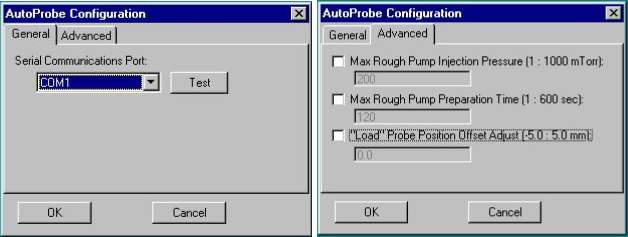
Figure 2 - AutoProbe configuration
The settings in the Advanced screen will probably not need to be changed, but they can be changed if necessary.
The one value that may need to be changed here is the Filament "Load" Position. This "Load" position adjustment allows you to position the probe directly under the syringe needle during sample loading. If the alignment of the needle is not correct, the linear position of the probe can be adjusted here to position the syringe needle precisely over the center of the DEP probe tip filament coil.
The "Max Rough Pump Injection Pressure" is the vacuum level to which the isolation valve pump must reach before the isolation valve opens and the probe proceeds in to the source. It is recommended that the value of 200 millitorr be used. The next line, "Max Rough Pump Pressure Time" is the time limit that the vacuum pump has to achieve the above set pressure. It is recommended that this time be set to 120 seconds. If the set vacuum pressure is not reached in the operation of the probe within the 120 seconds time (2.0 minutes), the probe will withdraw from the isolation valve and a vacuum leak warning message will be displayed in the status panel of Xcalibur on the AutoProbe Manual control window.
The screen shown below permits the AutoProbe method to be set up and saved. The AutoProbe method consists of 3 heating steps - Solvent Elimination - Sample Analysis - Bakeout.

Figure 3 - AutoProbe Window for entering AutoProbe method parameters
Solvent Elimination. Before the sample is analyzed, a small current can be passed through the DEP filament wire to slightly heat the wire and remove the sample solvent. If solvent removal is not required, then uncheck the "solvent elim." checkbox. This step of solvent removal can be done either in atmosphere (before the probe is injected into the vacuum system), or in the vacuum inside the mass spec (before the probe is mated up against the MS source). If the solvent removal is to be done inside the vacuum, then check the "Do solvent elimination in vacuum" checkbox, otherwise the default is for solvent removal to occur at the sample load position (at atmospheric pressure).
Sample Analysis. The DEP filament wire can be run at a constant current rate or with a ramp. Up to three different ramp steps are available. These multiple current ramps can be used in some applications to separate analytes in a sample based on boiling points. Just check the current steps desired in the boxes on the left.
Good results can be obtained by running the filament at a single ballistic constant high current of between 500 and 900 mA. This will provide for a quick heating and desorption of the samples into the mass spec source in the minimum amount of time. The result will be sharp total ion chromatograms and therefore the highest level of sensitivity.
Bakeout. The bakeout mode is used to clean the DEP probe tip between samples to prevent cross contamination of samples. After sample analysis, the probe retracts about 1.5 inches out of the source and the bakeout method occurs in the mass spec vacuum. Normally an isothermal setting of between 800 and 1000 mA for 15 seconds will thoroughly clean the DEP probe tip wire.
The Manual Control Window permits the control or operation of the AutoProbe manually. In some instances it may be necessary to move the probe against the MS source in order to seal the source tightly or align the syringe needle with the DEP wire coil. This can be accomplished in the Manual Control window.
 Figure 5 - Sample sequence and AutoProbe instrument run status.
One of the unique features of the Thermo Finnigan Xcalibur software is the ability to operate the mass spectrometer in an Open Access Mode. The Open Access System permits inexperienced chemists and technicians to submit samples directly to the mass spectrometer for analysis. The samples are then analyzed automatically and the results reported back to the chemist with little or no interaction of the mass spectrometer operator. The results are increased productivity from the mass spectrometer lab with less technical staff requirements.
The AutoProbe was integrated into this Open Access mode of operation within the Xcalibur software system. For a sample to be analyzed, the chemist fills out a simple form on a PC screen including the submitters name and sample name. He then selects a method of analysis from one of several standard methods preestablished by the supervisor. After completing the form, the user is instructed where to place his sample. The samples are then analyzed automatically with no operator intervention. The chemist has the option of having the results e-mailed back to him.
Figure 6 - Operation of the AutoProbe in Open Access
The AutoProbe can analyze sample sizes from 500 nanograms down to less than 1.0 nanograms in less than 1.0 minutes of MS analysis time. It requires about 2.0 minutes to inject the sample into and out of the MS vacuum system, for a total time of about 3.0 minutes between samples. In addition the AutoProbe technique has been shown to be very reproducible, quantitative and there are no "memory effects" with this technique.
Supplies
The AutoProbe™ System as shipped consists of the following. A quantity of one of each of the following is included unless otherwise noted below.
- AutoProbe Console with Adjustable Base
- CTC PAL AutoSampler
- Software
- SIS AutoProbe System Software Module CD
- PAL Driver for Xcalibur with Cycle Composer CD
- Edwards Vacuum Pump
- MS-Probe Interface Tube
- AutoProbe Accessories
- DEP Filament (2 included)
- Source Position Calibration Tip (1 included)
- Probe Seals (1 spare set included)
- Isolation Valve Seal Set (1 spare set included)
- One Sample Tray and one Pump Tray
- Compressed Air Gas Line - 1/8" O.D. x 20 feet flexible nylon air line
- AutoProbe Cables
- Serial Cable - PC to AutoProbe
- Serial Cable - PC to CTC PAL Autosampler
- Remote Start Cable - AutoProbe to MS
- AutoProbe IO Cable - AutoProbe to CTC PAL AutoSampler
- CTC Low Voltage Power Cord
- Main Power Cord for AutoProbe
Accessory Tools
- Allen Wrenches
- Probe Seal Removal Tool
Manuals
- SIS AutoProbe Manual
- CTC PAL Autosampler Manual
Optional Accessories - (must be purchased separately)
- PC Serial Port
Recommended Spare Parts (must be purchased separately)
- DEP Probe Filaments
Probe Seals
Isolation Valve Seal Set
References
- AP2000 AutoProbe Brochure (PDF)
- AP2000 AutoProbe Manual
- For additional details, pricing and ordering information, contact us
Articles and Application Notes
 Note 87: Design and Development of an Automated Direct Probe for a Mass Spectrometer Design and Development of an Automated Direct Probe for a Mass Spectrometer
- Note 89: Quantitation of Organics via a Mass Spectrometer Automated Direct Probe Quantitation of Organics via a Mass Spectrometer Automated Direct Probe
 Note 90: An Automated MS Direct Probe for use in an Open Access Environment An Automated MS Direct Probe for use in an Open Access Environment
- Note 91: AutoProbe DEP Probe Tip Temperatures AutoProbe DEP Probe Tip Temperatures