- ▶
- Heaters/Source
- ▶
- Agilent Heaters and SensorsMass Spectrometry, Scientific Supplies & ManufacturingScientific Instrument Services 5973 Source Heater Tamper Resistant Allen Wrench 5973/5975 Quad Sensor 5985 Source Heater Assembly Agilent Interface Heater Assembly 5971 Interface Heater

- ▶
- TD
- ▶
- TD-5 (single sample) (This Page)


A Short Path Thermal Desorption (SPTD) system for the analysis of volatiles and semi-volatiles by GC and GC/MS.
Description
The SIS TD-5 is a "short path" thermal desorption system. It provides unattended thermal extraction (thermal desorption) and injection of volatile and semi-volatile organics from solid, liquid and gas samples into a gas chromatograph (GC). The system delivers samples into the GC along an optimal “short path,” thereby eliminating transfer lines and cross-sample contamination issues found in previous systems.
A sample for analysis is introduced into a desorption tube, which is then fitted with a needle and attached to the TD-5 Desorption Unit. The Desorption Unit sits over the GC injection port, where, upon signal from the PC software, it automatically injects and desorbs the sample into the GC injection port and column using the temperatures and times prescribed in the desorption method.
The TD-5 System consists of the Desorption Unit (which contains the sample analysis hardware), an Electronics Console (which contains a microprocessor and power supply), and a Windows- based Thermal Desorption software (which provides control and monitoring of the system). This software can be fully integrated with selected GC data systems (e.g. Agilent ChemStation), or it can operate fully independently from the GC data system. Various accessories are available such as the Cryo-Trap, which cryogenically cools and rapidly heats the GC column head for improved chromatographic resolution.

TD-5 system on an Agilent 6890 GC.
The Short Path Thermal Desorption System provides several unique advantages over other desorption systems:
- It enables the sample, which is trapped on an adsorbent media contained in a Silco Coated SS (desorption tube), to be subjected to rapid heating.
- The desorbed component can be easily and efficiently transferred into the injection port of the gas chromatograph from a glass lined stainless steel sample tube and its associated injection needle. This provides for a short transfer path for the sample in an inert environment to minimize the degradation of labile sample components which often decompose upon contact with the hot catalytic metal wall surfaces of the transfer path of other systems.
- Third, each sample has its own individual adsorbent trap tube and needle to eliminate the possibility of cross-contamination from sample to sample, thus preventing any "memory effect" due to overloading of the sample in the Silco Coated desorption tube or due to residues from previous samples.
Features
- High sensitivity Thermal Desorption and Direct Thermal Extraction of solid, liquid, and gas samples
- No memory effects – each sample has its own independent and “short” flow path from sample to GC, eliminating transfer lines as a source of contamination
- Stainless steel sample tubes (or silco treated) are inert to samples and strong for sample handling and transporting.
- Rapid cryogenic (CO2 or LN2) cooling and heating of the GC column head for improved chromatographic resolution (optional Cryo-Trap™ accessory).
- Mounts overtop most GC injection ports—easily removable and transferable.
- Automatic injection and desorption of sample into GC (pneumatic driven injector).
- Windows-based software for control and monitoring of the system.
- Seamless integration into Agilent ChemStation™ and Thermo Fisher Scientific Xcalibur™
- Optional - stand alone operation with other top injecting GC’s
- Desorption: temp range: 20 ° to 400 °C, either isothermal or temperature programmed. Max heat rate: 100 °C/min.
- Cryo-trap: min temp: -70 °C (CO2) or -180 °C (LN2). Max temp: 400 °C. Max heat rate: 10 °C/sec.
Specs
| Desorption Unit Weights and Dimensions | |
|---|---|
| Weight: | 17 lbs |
| Size: | 5.5" wide x 6.5" deep x 22" high |
| Carrier Gas (Helium or Nitrogen) | 40-60 psi, 100 cc/min max (0.04 cfm) |
| Compressed Air | for gas valve operation, Laboratory Supply or Cylinder, 60 psi, 100 cc/min max (0.04 cfm) |
| Electronics Console Weights and Dimensions | |
| Volts AC | 115 +/- 10%, 10 amp max. |
| Temperature Controller | |
| Heater Output: | 115 Volt, 600 Watt |
| Input | Platinum Resistance Thermometer (PRT) |
| Heater Cartridges: | 115 Volt, 300 Watt ea., x2 |
| Temperature Range: | 20 degrees to 350 degrees C |
| Temp. ramp: | 0 to 100 degrees C/min |
| Cryo-Trap Heater | |
| Heater Output | 18VAC |
| Inpu | TC |
| Range: | 0 to 400 degrees C |
| Cryo-Trap Cool Valve | |
| Output: | 110V |
| Temperature Range: | CO2 (0 to -70 degrees C); LN2 (0 to -180 degrees C) |
Applications
Thermal Desorption (Purge & Trap)
Environmental Air Analysis
Flavor and Fragrance Analysis
Off odor/Off-Flavor Analysis
Forensic Arson Analysis
Residual Gas, Solvents and Chemicals in:
Pharmaceuticals
Packaging Materials
Building Products
Food Products
Natural Products
Direct Thermal Extraction of:
Plastics
Synthetic Fibers & Materials
Spices
Natural Products
Pharmaceuticals
Finished Products
see also the Complete List of Application Notes.
What do you want to analyze? View application notes on Arson, Air (Pollution, Airplane, Automobile, Vacuum Pumps), Beverages (Carbonated, Milk, Wine, Coffee), Carpet, Chewing Gum, Clothing, Cologne/Perfume, Cooking Oils, Explosives, Flowers, Food Packaging, Plastic Wraps, Fruit (Blueberry, Peaches, Cranberries), Electronic Components, Paint (Latex, Oil-base), Soil, PCB, PNA, Food (Spices, Pepper, Tea, Honey, Mushrooms, Rice, Truffle Oil), Plants, Pharmaceuticals, Printer Toner, Tires, Full List (60+).
Theory of Operation
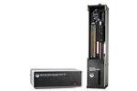
The Thermal Desorption Unit sits directly on top of the injection port of most GC's, where it provides direct desorption of both volatile and semi-volatile samples into the GC injection port and column. The system delivers samples into the GC along an optimal “short path,” thereby eliminating transfer lines and cross-sample contamination issues found in previous systems.Samples to be analyzed are collected into stainless steel desorption tubes (or silco-treated)(Fig.1A). A solid sample of inter-est may be packed directly into the tube and subjected to direct thermal desorption. Alternately, the tube may be packed with adsorbent resin such as Tenax™ TA or activated carbon for indirectly trapping analytes from liquid or air samples.
Fig. 1A Desorption Tubes can be packed with an adsorbent resin or with solid matrix samples.
Fig. 1B

To analyze a prepared desorption tube (Fig.2), a syringe needle is first attached to the desorption tube, which is then attached to the connector tube on the Desorption Unit (#1). The desorption blocks heat to initial temperature (#2). Carrier gas is sent through the desorption tube for an initial purge time (#3). The system then injects the desorption tube into the GC injection port (#4) where flows are readjusted as required by the method of analysis, i.e. split/splitless,etc. The hinged heating blocks close around the desorption tube (#5) to ballistically heat the sample tube, optionally with a temperature ramp. The combination of the heat applied and the carrier gas flow through the desorption tube will purge the desired components into the GC injection port and onto the front of the GC column. To obtain sharp chromatographic peaks when desorption typically lasts 5 to 15minutes, it can be desirable to focus desorbed components at the head of the GC column. This focusing can be improved by installing a Cryo-Trap, which cryogenically cools the head of the GC column(with liquid CO2 or LN2) during desorption to trap desorbed analytes.After desorption, the Cryo-Trap rapidly heats to volatilize the trapped analytes and quickly release them through the GC column for separation (#6).
Fig 2.


A Complete Description of the Theory of Operation is presented in Technical Bulletin No. 1.

When ready to be analyzed, a syringe needle is attached to the desorption tube which is then attached to the connector tube on the Auto injector Assembly of the Desorption Unit.
Purging: The carrier gas through the Desorption Unit is turned on via the electronics console microprocessor and the flow through the desorption tube is adjusted via the flow controller, rotameter and/or the pressure transducer between 1.0 mL/min and 120 mL/min.

Injecting: The desorption tube is injected with the needle attached. The desorption tube will pass through the opening in the middle plate of the Desorption Unit base to position the desorption tube in proper alignment with the GC injection port and the normally open desorption block assembly.
When injection is complete, the flows are readjusted as required by the method of analysis, i.e. split/splitless, etc. In this position the sample is not being desorbed into the GC since the heating blocks have not yet closed around the desorption tube. The temperature of the tube remains close to room temperature due to the action of the cooling fan, which pulls in room air from the front of the Desorption Unit, thru the view port and across the desorption tube. Carrier gas flows, desorption temperatures, and GC parameters can be adjusted as required.
Blocks close and desorption: The Microprocessor Control actuates an air valve which delivers air to the air powered solenoid and moves the hinged heating blocks from the open to the closed position around the desorption tube. The desorption tube will ballistically heat up to the set temperature or the temperature program program ramp for the heater blocked will begin. The combination of the heat applied and the carrier gas flow through the Desorption Tube will purge the desired components into the GC injection port and onto the front of the GC column.
The various parameters are set and utilized according to the application requirements. Normally desorption temperatures between 70 degrees C and 250 degrees C are suitable for most applications. The maximum desorption temperature permissible with the system is 400 degrees C.
The heater blocks can be temperature programmed at ramp rates up to 100 degrees/min. Normal desorption times vary from 3 minutes to 15 minutes, however longer desorption times up to 100 minutes are permitted. Since the column is normally maintained at sub ambient temperatures, the desorbed compounds of interest are trapped on the front of the GC column in a narrow band utilizing GC oven cooling or the GC Cryo-Trap Accessory. Despite the long desorption times, the peaks eluted from the column are extremely sharp and well resolved.
Desorption complete, cryo-heat, GC start: After the desorption is complete, the desorption heater blocks are opened, the normal carrier gas flow to the GC injection port is turned on, and the GC, Mass Spec, GC Cryo-Trap Accessory is switched to the heating mode and recorders are started via accessory ports on the back of the Electronics Console cabinet which act as remote out switches.
The temperature and time parameters are configured in the software.
Software
The SIS Thermal Desorption Software included provides visualization and control of all thermal desorption operations through a user-friendly graphical user interface. The user may configure system and thermal desorption methods settings (e.g. times and temperatures) as well as monitor the system status (e.g. temperatures and pressures) during a run.
The Thermal Desorption Software can be used fully independent of the GC data system, or it can be fully integrated with certain GC data systems (e.g. Agilent ChemStation™ or ThermoXcalibur™ ). When the software is integrated with ChemStation, MassHunter, and Xcalibur™ thermal desorption parameters get stored directly into the current ChemStation method so that GC and thermal desorption method settings are linked. The run is initiated from ChemStation, and methods may be changed between samples to provide different desorption parameters for different samples. For example, a separate high temperature bake out or blank method can be setup and run between samples to assure the system is clean for the next sample. The software operates Microsoft Windows operating systems.
Features:
- Configure system parameters and limits
- Configure thermal desorption methods including desorption and cryo-trap times and temperatures.
- Monitor system status including actual times, temperatures, pressures and status during a run.
- Log sample status and errors.
- View online help system.
- RS-232 (optional USB bridge) communication with TD-5 instrument.
- Optional Agilent ChemStation, MassHunter or Thermo Xcalibur integration for method load/save and sample run.
- The Cryo-Trap may be operated separately for syringe injections

Figure: Thermal desorption control software showing the
configuration of parameters for a thermal desorption method.
Here, times and temperature set-points are specified.
These are displayed graphically on the right side.

Figure: Thermal desorption control software showing a
run in progress. Shown are the time sequence of the desorption process and
the temperature program (Method parameters), the history of previous
samples run (Sample Log Book), and the status of the current run (times,
temperatures, pressures, and animated graphic of the desorption system).
Thermal Desorption Electronics Console
The Electronics Console consists of a user adjustable microprocessor electronics control which is interfaced via a 20 pushbutton keypad with a yellow fluorescent display to control the operation of the desorption system. The Main Power Switch controls the power to the entire Desorption System. The Heater Switch turns on the power to the heater cartridges in the desorption tube heater blocks and begins their heating cycle. The Cryo-Trap heater switch controls the power to the circuit for the GC Cryo-Trap Accessory Unit. A Platinum Resistance Thermometer (PRT) in the heater blocks provides for the accurate (+/- 0.1%) temperature readout and also provides for feedback to the temperature controller to maintain the heater block temperatures.
A single cable assembly provides the connection between the Electronics Console and the Desorption Unit. The cable has connectors on each end which screw into the electrical feedthru fittings located on each of the two assemblies. The cable can be used reversibly since the connectors on both ends are identical.
The TD-5 Controller automatically controls both the cooling and heating of the GC Cryo-Trap accessoty.
References
Purchasing
When ordering the Short Path Thermal Desorption System, a wide range of systems and accessories are available depending on the application requirements of the user. A minimum system should include the Thermal Desorption System (Part #785000) and an installation kit for your make and model of gas chromatograph. Installation and training is recommended at the prices listed below. Alternatively, training is available at S.I.S. at no charge. The items marked “recommended” will make operation and use of the Short Path Thermal Desorption System easier and more convenient. The items marked “optional” should be purchased only if an application which requires it is contemplated.
- Minimum System - A minimum
System should consist of the following:
Part # 785000 Complete Short Path Thermal Desorption System, Model TD5 Part # 7852__ Installation Kit, select one of the 6 available Kits - Recommended Starter Options:
Part # 781051A Desorption Tube Conditioning System - Necessary to assure clean desorption tubes and needles Part # 784010 Accessories Supplies Kit - A kit of needles, tubes and seals to get you started Part # 975000 Cryo-Trap Accessory - for Cryo-focusing volatiles at the front of the GC column
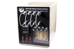 Sample Collection Oven This Sample Collection System permits the purging of volatiles and semi-volatile components present in solid materials and their trapping on Desorption Tubes packed with an adsorbent resin for subsequent analysis by desorption utilizing the Short Path Thermal Desorption System.
 Other Operating Accessories Accessories for SIS Short Path Thermal Desorption Systems (TD-5 and AutoDesorb).
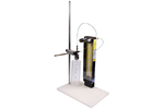 Purge and Trap System The Purge and Trap System consists of two single-ball rotameters with adjustable needle valve mounted on a nylon plastic base with an 18" long mounting rod support.
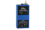 Air Sampling Pump The LFS-113 provides for constant flows between 5 to 200 mL/min at variable back pressures up to 25" of H2O for use in pumping air or gas samples through the S.I.S. Short Path Thermal Desorption Sampling Tubes.
 Adsorbent Resins A wide variety of adsorbent resins are available from many suppliers and manufacturers.
| Part No. | Description | Quantity In Stock |
Price EA |
Order |
|---|---|---|---|---|
| 785000 | Short Path Thermal Desorption (TD5) | 0*Lead time for this non-stock item is approximately 28 days. | CALL | |
| Training | ||||
| 782100 | On Site training and installation of TD-5 System, Includes 1 1/2 days on site, travel and all other expenses. (Continental US, except NJ & Eastern PA) | DISCONTINUED | --- | --- |
| 782110 | On Site training and installation of TD-5 System, Includes 1 1/2 days on site, travel and all other expenses for NJ & Eastern PA. | DISCONTINUED | --- | --- |
| Installation Kits - Select one - one required for each TD5 system | ||||
| 785200 | Varian 3400 GC Installation Kit, includes GC Carrier Gas Valve, remote start cable, desorption tube pliers, PTFE tubing, one desorption tube, needle and seals | 0‡Lead time for this non-stock item is approximately 7 days. | $405.00 | |
| 785210 | Agilent Technologies 5890 Series I GC Installation Kit, includes GC Carrier gas valve, remote start cable, desorption tube pliers, one desorption tube, needle, seals, septum adapter, mounting plate, PTFE tubing | 0§Standard lead-time for non-stock items is approximately two weeks depending on the item. | $550.00 | |
| 785220 | Agilent Technologies 5890 Series II, No EPC Installation Kit, includes GC Carrier gas valve, remote start cable, desorption tube pliers, one desorption tube, needle, seals, septum adapter, mounting plate, PTFE tubing | 0§Standard lead-time for non-stock items is approximately two weeks depending on the item. | $550.00 | |
| 785230 | Agilent Technologies 5890 Series II, with EPC Installation Kit, includes GC Carrier gas valve, remote start cable, desorption tube pliers, one desorption tube, needle, seals, septum adapter, mounting plate, PTFE tubing | 0§Standard lead-time for non-stock items is approximately two weeks depending on the item. | $860.00 | |
| 785231 | Agilent Technologies 6890 Installation Kit includes GC Carrier gas valve, remote start cable, desorption tube pliers, one desorption tube, needle seals, septum adapter, PTFE tubing | 0§Standard lead-time for non-stock items is approximately two weeks depending on the item. | CALL | |
| 785240 | Perkin Elmer 9000GC Installation Kit, includes GC Carrier gas valve, remote start cable, desorption tube pliers, one desorption tube, needle, seals, septum adapter, mounting plate and PTFE tubing | 0§Standard lead-time for non-stock items is approximately two weeks depending on the item. | $445.00 | |
| 785241 | Perkin Elmer Autosys XL Installation Kit, includes GC Carrier gas valve, remote start cable, desorption tube pliers, one desorption tube, needle, seals, septum adapter, mounting plate and PTFE tubing | 0§Standard lead-time for non-stock items is approximately two weeks depending on the item. | $865.00 | |
| 785250 | Shimadzu 17A GC Installation Kit, includes GC Carrier gas valve, remote start cable, desorption tube pliers, one desorption tube, needle, seals, septum adapter, PTFE tubing | 0§Standard lead-time for non-stock items is approximately two weeks depending on the item. | $865.00 | |
| 785260 | Finnigan GC Installation Kit, includes GC Carrier gas valve, remote start cable, desorption tube pliers, one desorption tube, needle, seals, septum adapter, PTFE tubing | 0§Standard lead-time for non-stock items is approximately two weeks depending on the item. | $935.00 | |
| 785261 | TG T2000 GC Installation Kit, includes GC Carrier gas valve, remote start cable, desorption tube pliers, one desorption tube, needle, seals, septum adapter, PTFE tubing | 0§Standard lead-time for non-stock items is approximately two weeks depending on the item. | $865.00 | |
| 785265 | CE 8000 GC Installation Kit, includes GC Carrier gas valve, remote start cable, desorption tube pliers, one desorption tube, needle, seals, septum adapter, PTFE tubing | 0§Standard lead-time for non-stock items is approximately two weeks depending on the item. | $970.00 | |
| 785270 | Varian GC Installation Kit, includes GC Carrier gas valve, remote start cable, desorption tube pliers, one desorption tube, needle, seals, septum adapter, PTFE tubing | 0§Standard lead-time for non-stock items is approximately two weeks depending on the item. | $865.00 | |
|
* Lead time for this non-stock item is approximately 28 days. † Call for availability. ‡ Lead time for this non-stock item is approximately 7 days. § Standard lead-time for non-stock items is approximately two weeks depending on the item. | ||||
|
|
||||
Additional Installation Kits for other makes and models of GC's will also be made available. Call for pricing and availability.
 Short Path Thermal Desorption Accessories Supply Kit When ordering the Short Path Thermal Desorption System, a wide range of systems and accessories are available depending on the application requirements of the user.
Product Brochure
(PDF) SIS Thermal Desorption Control Software
(TD5/AutoDesorb)Operates the TD system from a Windows PC. Fully integrated with the Agilent ChemStation software.- Thermal Desorption System Accessories Accessories for SIS Short Path Thermal Desorption Systems (TD-5 and AutoDesorb).
 Installation instructions on Varian, Agilent, and other GCs SITE PREPARATION Space Requirements The Short Path Thermal Desorption System is a compact, self contained injection system and desorption system that requires a minimum amount of space. The system is designed only for top injecting GC systems. The Thermal Desorption Unit sits directly over the injection port of the Gas Chromatograph. The base of the Thermal Desorption Unit is only 5.5 inches wide x 6.5 inches deep and the overall height is 22 inches. The Electronics Control System is 7 inches w...
Short Path Thermal Desorption Accessories Supply Kit 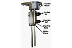 SIS 2-Inch CryoTrap for the AutoDesorb System
 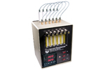 Thermal Desorption Conditioning Oven - 6 Tube SIS Purge and Trap System
  Short Path Thermal Desorption Tubes
  Aluminum Funnel for Loading Packings into Desorption Tubes
  Small Sample Spatula