- ▶
- Heaters/Source
- ▶
- Agilent Heaters and SensorsMass Spectrometry, Scientific Supplies & ManufacturingScientific Instrument Services 5973 Source Heater Tamper Resistant Allen Wrench 5973/5975 Quad Sensor 5985 Source Heater Assembly Agilent Interface Heater Assembly 5971 Interface Heater

- ▶
- MultipliersAgilent/HP Amptek Anelva Bear BioRad/Ciphergen Bruker Cameca Comstock CVC 1100 Dune DuPont Extrel FEI GBC Griffin Hiden Hitachi Inficon(Balzers/Leybold) JEOL LKB Mass Analyzer Products Mass Sensors McCallister Nermag Nu Inst Orbital Omicron PerkinElmer Riber Sciex/AB Seiko Sensar Shimadzu (Kratos) Standford Teledyne Thermo/Finnigan Ulvac UTI/MKS Vacuum Tech Varian Vestec Viking Waters/Micromass/VG Generic Catalog Page A40 Catalog Page A41 Catalog Page A42 Catalog Page A43 Catalog Page A36
- ▶
- Griffin (This Page)

Features
For instruments: Griffin Analytical Minotaur Mass Spectrometer
- High Sensitivity
- Stable Glass Surfaces
- High Gain
- High Reliability
- Best Value
- Long Life
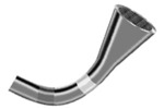
DeTech offers the widest range of Channel Electron Multipliers for the major Mass Spectrometers. Detech multipliers are manufactured from a lead glass suitably processed to yield an efficient secondary emitting layer on the inner surface. Each electron multiplier is delivered with a quality control label indicating its model number, test voltage, bias current at the test voltage and the date of shipment.
Description
For instruments: Griffin Analytical Minotaur Mass Spectrometer
The manufacturing process of electron multipliers utilizes a number of glass forming and wet chemistry techniques. All multipliers are manufactured from a specialty lead silicate glass formula developed by Detector Technology, Inc.Technical
Instructions for Basic Care of Channel Electron Multipliers:- Store detectors out of sunlight, sealed in nitrogen filled bag.
- When installing the detector into an instrument, use powder-free finger cots or gloves.
- Before running samples follow the preconditioning procedure.
- If the detector becomes contaminated with dust or oil, clean in isopropyl and dry in a 150 °C oven for 30 minutes.
Cleanliness – In the event that a multiplier becomes contaminated with lint, dust, or other particulate the multiplier should be flushed with either isopropyl or methanol. The unit can then be blown with dry nitrogen and baked at 150°C until dry. Multipliers should not be cleaned in any acid, this would have a detrimental effect on its lifetime and performance.
 Collection
Efficiency - Collection efficiency is the ability to detect an
input event and convert that event into output signal. Ion optics play
a major role in attaining good collection efficiency. If signal is lost
during the first strike stage results will be inaccurate. When an input
event strikes the surface of the cone secondary electrons are created.
These electrons should travel down the channel and strike the emissive
surface creating more electrons. If the first strike electrons exit the
cone then the detector will have poor collection efficiency. There are
two solutions to this problem. A grid can be placed on the cone. The grid
acts as a barrier between any outside potentials that may attract the
secondary electrons. It forces the electrons to travel down the channel.
The second option is to add focusing plates to the input ion stream. If
the plates are placed properly the first strike event will occur at the
apex of the cone. The secondary electrons will then be created deep enough
in the voltage gradient that they will travel down the channel. By improving
collection efficiency signal to noise will increase and data analysis
will be more accurate.
Collection
Efficiency - Collection efficiency is the ability to detect an
input event and convert that event into output signal. Ion optics play
a major role in attaining good collection efficiency. If signal is lost
during the first strike stage results will be inaccurate. When an input
event strikes the surface of the cone secondary electrons are created.
These electrons should travel down the channel and strike the emissive
surface creating more electrons. If the first strike electrons exit the
cone then the detector will have poor collection efficiency. There are
two solutions to this problem. A grid can be placed on the cone. The grid
acts as a barrier between any outside potentials that may attract the
secondary electrons. It forces the electrons to travel down the channel.
The second option is to add focusing plates to the input ion stream. If
the plates are placed properly the first strike event will occur at the
apex of the cone. The secondary electrons will then be created deep enough
in the voltage gradient that they will travel down the channel. By improving
collection efficiency signal to noise will increase and data analysis
will be more accurate.
Conversion Dynodes - The primary advantage for utilizing a conversion dynode is to increase the secondary emission characteristics of heavier ions. Since conversion dynodes can operate anywhere between 5 and 50 KV, the attraction of the heavier ion is greater thus an increase in the secondary emission ratio occurs. In addition, the mass discrimination in the multiplier is reduced. If the conversion dynode is set for positive ion detection, there is a negative high voltage placed on the dynode. When the ion strikes the dynode, secondary electrons are created, thus being attracted to the multiplier. For negative ion detection, a positive ion is produced from the surface and detected by the electron multiplier. The positive ions are produced primarily by secondary ion emissions (sputtering) either from the metal (of which the conversion dynode is constructed) or the gasses absorbed on its surface. DeTech manufactures several types of dynodes, created from several different materials. We have full capability of testing dynode multiplier configurations in positive and negative ion mode at voltages up to +/- 30KV. Please contact a DeTech engineer for more information or design ideas.
Dark Noise - Noise is considered to be any unwanted signal seen. Generally noise can be broken down into two categories, dark counts and dark current.
Dark counts occur when an input event causes the multiplier to create a pulse of electrons. A properly functioning multiplier will not create electron pulses without an input event. When this type of noise occurs, it is typically caused by the environment the unit is in. Dirty source, high pressures, and neutrals are a few things that may cause this type of noise. Detector Technology tests 100% of its product to ensure that the multipliers are working properly and are not creating dark counts.
Dark current is generally caused by microphonics. This occurs when electronic signals are placed in close proximity. Crosstalk and voltage arcing are two of the major causes of dark current. The best method to decrease microphonic noise is to increase shielding around the signal lead of the electron multiplier. Detector Technology builds its product with this in mind. Many of our models include shielding to decrease any possible microphonic noise.
Detection Schematics - There are many ways to run an electron multiplier. Below is a sample of various ways to run a unit based on either positive or negative ions in various modes. Please consult with a DeTech engineer for any installation questions.
Full Width Half Maximum (FWHM) - Full width half maximum is a measurement describing the width of the pulse height distribution in pulse counting applications. It is mathematically expressed as:
FWHM=Peak Gain Value/GainValue at half peak height X 100
When using a channel electron multiplier in pulse counting applications it is advised to use a multiplier with a FWHM of 150% or less. In pulse counting applications it is important to have a multiplier capable of producing pulses with similar amplitudes.
Gain – The gain of a multiplier is defined as the ratio of the output to input. This can be measured in terms of counts or current. For counting, each input event creates one charged pulse, which is treated as one count. The intensity of the pulse is the gain of the multiplier. For current mode, an average input and output current is measured. The ratio of the output to input current determines the gain. The method chosen is based on the application and on the style of multiplier used. Usually when the multiplier gain is less than 106 then current measurements are preferred. If the gain is higher than 106 then either counting or current measurements may be taken.
 High
Pressure Operation – In several detection applications it
is necessary to operate at elevated pressures such as 10-4 – 10-2
Torr. Traditionally channel electron multipliers are not able to function
efficiently at these pressures because of ion feedback. Detector Technology
has developed an unconventional style of channel electron multipliers
that has the capability of operating in this high pressure range.
High
Pressure Operation – In several detection applications it
is necessary to operate at elevated pressures such as 10-4 – 10-2
Torr. Traditionally channel electron multipliers are not able to function
efficiently at these pressures because of ion feedback. Detector Technology
has developed an unconventional style of channel electron multipliers
that has the capability of operating in this high pressure range.
The Series 2000 is a multi-channel detector that has internally twisted channels. The tightly twisted channels prevent ion feedback. Ion feedback occurs when residual gases travel down the channel and strike the emissive surface. Secondary electrons can be released causing noise and decreased lifetime. At higher pressures more residual gases reside in the channel, by tightly twisting the channels the residual gases are not able to gain enough kinetic energy to create secondary electrons. Therefore, noise is eliminated and lifetime is increased.
Hystereses - When an electron
multiplier is subjected to a large input it has the potential to go through
a period of dead time before the next pulse can be detected. This phenomena
is called Hystereses.
One way to improve upon Hystereses is to increase the resistance in the detector. This will allow the detector to operate at a cooler temperature and be less susceptible to voltage shifts within the multiplier during high gain amplification. The tradeoff with increasing the resistance is the reduction in the dynamic range of the multiplier.
Internal Bias Resistor - The channel electron multipliers manufactured by Detector Technology include a self biasing resistor. This is most useful when using the multiplier in EIC applications. The internal bias resistor is located towards the back end of the channel and can be seen on the outside of the tube. It appears to be black rather than silver. This resistor is manufactured to be 3 – 5% of the overall resistance of the detector. It is used to bias the back of the channel so exiting electrons are attracted to the collector plate.
Lifetime – Multiplier lifetime is determined by two classic failure mechanisms: failure through electron depletion or through ion contamination. The mode of failure that occurs is related primarily to the vacuum pressure during operation. The magic pressure that separates the two modes of failure is 5x10⁻⁷ torr. Deeper vacuum pressures will see electron depletion failure and any higher pressure environments will see ion contamination.
Electron Depletion - In a contamination-free environment the lifetime of an electron multiplier has been found to depend upon the number of electron impacts per unit surface area. Therefore the lifetime of a multiplier is determined by the cumulative charge output. Experiments performed at Detector Technology have confirmed that the total charge of a multiplier is typically 4 coulombs before the lifetime is exhausted. This mode of failure is under ideal conditions, of vacuum pressure on the order of 5x10⁻⁷ torr or deeper. The typical area to fail is the back end of the multiplier where the most secondary electrons are released.
Ion Contamination - Since most mass spectrometers and residual gas analyzers do not operate under ideal vacuum pressures the mode of failure is not from electron depletion, but from ion contamination. In a non-ideal operational setting, electron irradiation can modify or otherwise damage the surface through a variety of mechanisms. The net effect can be one or more of the following:
- Changes in surface composition
- Structural modifications or damage
- Electron charging and heating
The main concern is the possible effects of electron stimulated desorption (ESD), electron stimulated adsorption (ESA), and electro migration. All three phenomena can oxide the surface, deposit carbonaceous layers on the surface, or influence the concentration and depth distribution of alkali ions in the reduced layer. Once this occurs and the surface composition is affected the surface work function can be dramatically decreased, thus causing a loss in gain and concluding in a loss of lifetime.
The input end of the multiplier can also be damaged through the impact of high molecular weight ions at high energies. These impacts can result in chemical changes in the glass surface and even physical sputtering which can reduce the effective sensitivity of the device.
Once a change in surface composition is created, then cleaning of the multiplier is very difficult. To prevent this effect, proper conditioning of the multiplier is critical to remove any loosely absorbed gasses on the surface prior to full operation. Also, operating at the best possible vacuum pressure will also increase lifetime tremendously.
 Multiplier
Operation – DeTech multipliers are manufactured from a lead
silicate glass that is processed to have secondary emissive and resistive
properties. When the interior surface is struck by an ion, electron or
photon secondary electrons are released. The voltage applied to the multiplier
causes the secondary electrons to travel down the channel. Eventually,
the secondary electrons will strike the emissive surface again, causing
the release of subsequent electrons. The electrons are eventually collected
at the output end of the multiplier. This signal is fed into the appropriate
electronics.
Multiplier
Operation – DeTech multipliers are manufactured from a lead
silicate glass that is processed to have secondary emissive and resistive
properties. When the interior surface is struck by an ion, electron or
photon secondary electrons are released. The voltage applied to the multiplier
causes the secondary electrons to travel down the channel. Eventually,
the secondary electrons will strike the emissive surface again, causing
the release of subsequent electrons. The electrons are eventually collected
at the output end of the multiplier. This signal is fed into the appropriate
electronics.
Multiplier Resistance - Electron
multiplier resistance plays a significant role in the multiplier’s
performance when dynamic range is of concern. DeTech has the capabilities
of manufacturing multipliers with various resistance ranges based on the
glass compositions selected.
I (linear output) = (E / R) * .10
Where: E = Applied voltage (volts)
I = Linear output current (uA)
R = Resistance (MW)
The resistance decreases when the operating temperature
increases. Therefore, the bias current increases for a given applied voltage.
This results in a proportionate increase in dynamic range.
Multiplier Terminology - Below is a schematic of a typical electron multiplier and terms that are often used to refer to features and components of their assemblies.
 Non-Conductive
Zone - On the outside of the detector there is a section of the
multiplier surface that appears to be rough in texture. This is the non-conductive
zone. The multiplier surface is resistive because of the special processing
that it goes through during manufacturing. A section of the resistive
layer is removed so that high voltage can be applied to the multiplier
and the current flows down the internal channel. If this area was left
resistive then the multiplier would not work efficiently. The multiplier
would act as a current divider and the performance of the channel would
be effected.
Non-Conductive
Zone - On the outside of the detector there is a section of the
multiplier surface that appears to be rough in texture. This is the non-conductive
zone. The multiplier surface is resistive because of the special processing
that it goes through during manufacturing. A section of the resistive
layer is removed so that high voltage can be applied to the multiplier
and the current flows down the internal channel. If this area was left
resistive then the multiplier would not work efficiently. The multiplier
would act as a current divider and the performance of the channel would
be effected.
Pre-Conditioning – In order to maximize the lifetime of a multiplier it should be pre-conditioned. During this process loosely bonded water molecules are released from the surface. To perform preconditioning a multiplier should be placed under vacuum. It is recommended that a vacuum of 10-6 Torr or better be used. Once the appropriate vacuum is reached a small input should be applied to the multiplier. In counting mode approximately 15,000 counts/second is desirable. In current mode approximately .1uAmp is needed. The multiplier voltage should be slowly raised to reach an appropriate gain level. In counting mode this should be approximately 107. In current mode this should be approximately 105. The multiplier should be run in this state for several hours. This should be done in order to avoid a rapid release of water molecules. If the water molecules release rapidly then the multiplier surface can be permanently damaged, thus shortening the life of the detector.
Pulse Height Distribution (PHD) - Pulse height distribution is the graphical representation of the distribution of the amplitude of the pulses generated by an electron multiplier at a particular voltage. In pulse counting applications the graph appears to be quasi-Gaussian, or bell shaped. In analog applications the graph appears to be negative exponential.
Rise Time - The rise time is defined as the length of time it takes for the leading edge of the produced pulse to go from 10% to 90% of its maximum amplitude. Channel electron multipliers usually have a rise time of approximately 3-5 nsec. The rise time is determined by the length of the multiplier channel.
Shelf Life – It is ideal to store the multiplier in vacuum, but not required. DeTech lead glass multipliers are air stable devices that can be stored indefinitely, as long as the units are kept out of direct sunlight, dry, and kept in their original sealed bags prior to use. DeTech fully warranties all of its multipliers for shelf life.
Signal Connection - There are two methods for collection of signals for an electron multiplier: either a closed cap collector or an isolated collector. Below are the electronic schematics for both methods.
Vacuum Baking - Vacuum baking is used as a method of decreasing water molecule adsorption on the emissive surface of channel electron multipliers. When water molecules are on the emissive surface they are released during multiplier use. If the molecules are released too quickly permanent damage may occur to the emissive surface. When vacuum baking, Detector Technology recommends baking at no hotter than 250°C for 12-15 hours. During this time period water molecules are slowly released from the emissive surface in a safe manner. It is important to vacuum bake in a clean environment. If other materials are present in the vacuum bake outgas, the channel electron multiplier may adsorb these gases and the emissive surface could be adversely effected. Detector Technology recommends that all units be vacuum baked. This helps to precondition the unit and increase lifetime.
Warranty
Detector Technology’s philosophy of “Committed to Excellence” is backed with a 100% no-nonsense warranty. If any customer is not satisfied with a DeTech electron multiplier, the multiplier is replaced immediately with no questions asked and regardless how long the multiplier has been on the customer's shelf. During operation if you are not satisfied with initial operations we will replace under fully warranty. Based on long term usage of the Multiplier and the operating environment DeTech will review the extended warranty on a case by case basis.
DeTech multipliers are manufactured from a lead glass suitably processed to yield an efficient secondary emitting layer on the inner surface. Each electron multiplier is tested before shipment to ensure its performance is within specification. Each multiplier is delivered with a quality control indicating its model number, test voltage, gain at that voltage, bias current at the test voltage and the date of shipment.